You are using an out of date browser. It may not display this or other websites correctly.
You should upgrade or use an alternative browser.
You should upgrade or use an alternative browser.
AGND or GND
- Thread starter gripner
- Start date
- Status
- Not open for further replies.
donkeyahoy
Well-known member
Yes I do have a 1k pot I was trying to use. I was going by this suggestion to reduce noise, but now doesn't seem to go with the other circuit ideas. On hand at my disposal is 1k, 5k, or 10k, or can get whatever.
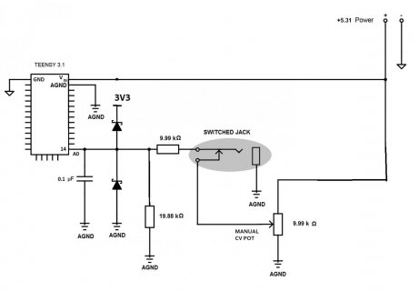
I set up a little prototype circuit with the power supply and resistors. Don't have the diodes or capacitor yet. This is the latest revision picture attached.
I also measured everything to see what the real life values are:
+5.31 V power
0-9.99 kΩ pot
9.99 kΩ res1
19.88 kΩ res2
I am getting 0-3.52 V results. My friend said to wire the diodes to the 3V3 on the Teensy and that will trim off the excess.
Thoughts on this latest revision?
Thanks again for the help! You will have your names in the credits!!

donkeyahoy
Well-known member
oh ... keep in mind that i can't just change the voltage divider circuit to get to the lower 3v3, because of the switched jack will sometimes use the 0-5V synth when plugged in. I suppose this is the essence of the dilemma.
thx
thx
Jp3141
Well-known member
You actually could use a different votlage divider -- say 9.99 k and 16k. Your max. would be about 3.2 V. Remember you can always scale the result with the ADC. e.g. even if the input only went from 0 to 2 V, you could scale by 1.65 to get full scale again.
Don't overly worry about noise -- jitter and imperfections in pot will be more troublesome.
Don't overly worry about noise -- jitter and imperfections in pot will be more troublesome.
donkeyahoy
Well-known member
You actually could use a different votlage divider -- say 9.99 k and 16k. Your max. would be about 3.2 V. Remember you can always scale the result with the ADC. e.g. even if the input only went from 0 to 2 V, you could scale by 1.65 to get full scale again.
Don't overly worry about noise -- jitter and imperfections in pot will be more troublesome.
i see how the 9.99 k and 16 k will give me 3.2 V max (from 5.31V power) with the pot which is good.
but when i plug in the synth into the jack (0-5V cv from synth) the results will be 3.1 V max.
i guess when i scale it with the programming one of the controls will have a dead zone at the top of the range where it reaches the peak earlier than the other, since the programming will not know which control is being used (its automatic with the switched jack). 0.1V may be too small to notice on the turning of the pot I suppose?
i think this will work then. unless you see something else that needs modifying.
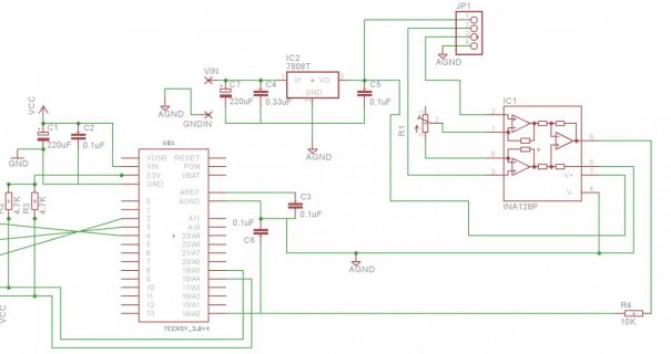
Think i will need some help. I ordered a PCB with the schematics posted earlier. I did some changes, basicly EVERYTHING, ina128, loadcell, lm7808 and components connected to them as capc are all connected to agnd. thus AGND is 100% seperated in my connections from GND. Everything is driven by power from lm7808 out and AGND (ina128 and loadcell) decupling is made from aref, A0 etc to agnd with caps.
There is nothing connected to GND thus USB gnd.
I still have the problem with different values depending on wich USB port I connect to and on wich PC i connect the usb to!.
The only thing i can think of is that the vref on the teensy3.0 gets different voltages from the onboard vregulator depending on the USB power/voltage.
I can not controll this!
But it is very easy to test if you have a multimeter/voltage meter good enough. 4 digits atleast.
Could you paul perhaps check?
Connect teensy board to one USB abd measure on aref pin (scetch use external aref)
connect to a totaly different USB and measure, do you get diff values on the instrument?
Are you powering everything from the USB or external power using the lm7808 to regulate the voltage? Also, what type of computers are you using? Laptops, desktops? Do these devices have an earth ground ( 3 prong plug)? You may be creating an ground loop, but may only be present on some computers depending on how they are powered. But from your schematic and post above, I can't quite figure out how exactly you have it all set up.
only the teensy is powered from usb- the rest is powered from lm7808 wich is powered by a 12V ac/dc power supply, with no earth/ground ac plug.
Computers i have tested with is laptop with ac/dc connected and alos without the ac/dc connected. no difference. also tried a panel PC with grounded ac/dc adapter
so, ac/dc, lm7808, ina128, load cell and all there caps are connected to agnd
A0, vraf have cap to agnd
teensy powered via USB. there is a 220uF electrolyt and 100nF ceramic paralel with the teensy3 5V and gnd aswell
agnd and gnd not connected together i my circuit

Last edited:
I still need some help from some one with a high res volt meter.
Need to have the aref value measured when the teensy3/3.1 is powered via a USB. And then move the teensy around between differetn USB ports/units to see how much the vraf differ. if any
thanks in advance.
Need to have the aref value measured when the teensy3/3.1 is powered via a USB. And then move the teensy around between differetn USB ports/units to see how much the vraf differ. if any
thanks in advance.
onehorse
Well-known member
A slightly different ground is the USB power ground -- this also has varying currents flowing in it and will have deviations from 0 V.
For instance, you might expect that an I/O pin driven to logic '0' will generate precisely 0 V -- it won't -- the internal driver connects this to VSS, and if with a good enough 'scope you could see the noise on this w.r.t AGND.
The Teensy chip will work well when these grounds are not equal; as long as the difference doesn't get more than a few 100 mV.
On the Teensy schematic, you will see that VREF is decoupled directly to VSSA (== AGND) with 0.1 uF. AGND and VSS are connected with a ferrite bead (to filter VSS noise from AGND).
So--in general--analog signals and things to do with ADC inputs should always be referenced to AGND. If the current they consume is small and doesn't change quickly (i.e. doesn't have a sharp clock), it might be OK to connect the power supply ground of these blocks to AGND also; if not, they should be powered from VSS/GND.
I think I understand the basic distinction between AGND and GND, but I still have a point of confusion I am hoping someone can help with. I am designing a LiPo charging shield that will take USB power to charge the battery, and allow the battery or USB to power the Teensy. My confusion is on how to treat AGND and GND. AGND is right next to VUSB and I logically thought of these two as a natural power source for the MAX1551 charging chip. I also thought it would be natural to connect AGND and GND to avoid differences in logic and analog reference voltages and avoid ground loops. With the discussion above (and elsewhere) I am unsure whether connecting the two grounds makes sense. Would someone please offer a recommendation (and an explanation!) Thanks.
Jp3141
Well-known member
For anything 'precise' (i.e. the ADC), the signal should be referred to AGND. For everything else, use GND.
AGND and GND are connected together on the Teensy board -- this is correct -- you should not also connect them together; it's unnecessary, and it is likely to add noise to the AGND line which would be bad.
Anything that runs an appreciable current (e.g. a charger, or a heavy load) would presumably not 'care' which ground it uses, and GND is suitable for this purpose.
Anything that runs an appreciable current (e.g. a charger, or a heavy load) would presumably not 'care' which ground it uses, and GND is suitable for this purpose.
Right, but anything drawing an appreciable current and not connected by room-temperature superconductors is injecting a voltage V = IR into the ground, where R is the trace and wiring resistance. That voltage can easily be many LSB change to an ADC, so keep it off AGND.
Theremingenieur
Senior Member+
That is explained on the first page of this discussion thread!
PaulStoffregen
Well-known member
GND is the normal ground. If you don't know which to use, always just use GND.
AGND is meant as a separate ground to be used only for sensitive analog signals. Even analog stuff works fine if it's grounded to regular GND. In some cases, using AGND allows a better measurement with analogRead(). Sometimes. But even in those cases, you can use GND.
If you're confused, the simple rule is to just use GND.
- Status
- Not open for further replies.

