Power Teensy 3.x from regulated 3.3V? / External Power while USB connected?

Status
Not open for further replies.

thinkpeace

Active member
I'm using a 3.3V power supply to provide power for a Wiz820 and an RFM69HW. Could I also power the Teensy 3.1 from the 3.3V regulated power supply, and bypass the on-board regulator?

I would also like to power the Teensy 3.1 externally while plugged into USB. I found this on the pjrc website, https://www.pjrc.com/teensy/external_power.html. It looks like a Teensy 2.0. I assume the same thing can be done with the Teensy 3.1, correct?

Thanks,

Eric
 
I'm using a 3.3V power supply to provide power for a Wiz820 and an RFM69HW. Could I also power the Teensy 3.1 from the 3.3V regulated power supply, and bypass the on-board regulator?

Yes, though you have to cut the VIN-VUSB pad connection on the underside of the teensy 3.x Once you do that, the external regulator can be attached safely to the 3.3V pins.

I would also like to power the Teensy 3.1 externally while plugged into USB.

No worries. Simply power your external regulator from the VUSB pin after disconnecting the VIN-VUSB connection as described above.

If you want to automatically choose among multiple power sources, simply use a 1A Schottky diode for every source. For example, one Schottky would connect the VUSB pin to your external regulator, another Schottky would connect a wall wart, etc.. Then, your external regulator would automatically choose the source with a higher voltage potential.

Alternatively, use a three pin header with the center pin connected to your external regulator. Each of the outer pins is connected to either VUSB or your battery pack, wall wart, etc. Then use a jumper shunt to switch and forth between the two voltage sources. Foolproof, but requires user-actuation (unlike the diode approach). On the plus side, less voltage drop and your can positively isolate power sources.
 
Last edited:
Simply power your external regulator from the VUSB pin after disconnecting the VIN-VUSB connection as described above.

If I cut the VIN-VUSB connection, wouldn't the VUSB pad go only to the USB connector?

If I have a regulated 3.3V power, I assume I could connect it to one of the 3.3V pads on the Teensy. Correct?

I don't plan on using diodes, I want to configure the Teensy for external power only. Though, if I did want to use diodes to power the Teensy from either power source, I assume I would need a 3.7-5.5V supply. It wouldn't work with a 3.3V power supply. Correct?

Thanks,

Eric
 
Now I understand what you are saying. I'm not using an external regulator, rather an external power supply. That is why I was confused about connecting to the VUSB pin. The answer to my first question is Yes.
 
Since I'm using a 3.3V power supply, I would need a four pin head to select between power source. VUSB, VIN, 3.3V & 3.3V supply
 
Since I'm using a 3.3V power supply, I would need a four pin head to select between power source. VUSB, VIN, 3.3V & 3.3V supply

All depends on how you want to configure your unit.

I use an external voltage regulator to make 3.3VDC for the K20. The power supply for the external voltage regulator comes either from a wall wart, the USB bus, or a serial header. You can use a pin in the shape of "T" to select safely among three sources, and one in the shape of a "+" to select among four external power sources using a shunt jumper, and have no pressure loss to worry about. The center pin would be attached to 3.3V in your application. By definition, all power sources would have to be safe for the K20 chip, i.e. none over 3.5V or so.

Usually, Schottky diodes work well when you start with higher voltages, like the USB bus or a 5V wall wart. Attach all these quasi-5V sources via Schootky diodes to the regulator and then the voltage regulator simply looks for the source with the highest voltage and draws from that.

Schottky diodes abate the voltage by between 0.3-0V, depending on the current flow, the capacity of the Schottky vs. the current drawn, and so on. In other words, they are great for an application where you will regulate power downstream.

For example, let's you have a 5V wall wart. Once it passes through the Diode, its voltage will be somewhere between 4.7 and 5VDC. Then your downstream voltage regulator will create a regulated 3.3V voltage source from that (it's good to have well regulated power source to ensure stable ADC measurements, among other applications). I regulate my power externally because I want to k20 chip as cool as possible and my external regulators are designed to handle noisy power sources, like the USB bus.

If you have an 3.3V external power supply that you trust (verify its no-load voltage does not exceed 3.5V) then you can certainly attach to the 3,3V pins directly, as long as you have cut the VUSB-Vin pad connection. Otherwise, your K20 voltage regulator (i.e. the one inside the K20) will fight with your wall wart every time the USB is plugged into the computer.
 
Last edited:
You will also need to power the Vin pad. If you don't power it you won't get any USB connectivity.

On one of my earlier revisions of my Wifi enabled board I did not power the K20 Voltage regulator thinking that my external Switch Mode 3v3 PSU would do it all, and could not understand why my USB was not working. Reading the Datasheet detailed that the K20 Voltage regulator also powers the USB module and with out this input the module is inactive.

So you can just put 3v3 onto VIN and the regulator will go into a bypass mode and allow you to power the k20 from an external 3v3 PSU.
 
Constantin, Thanks for your help.

I intend to have the Teensy & other component inside an enclosure screwed shut. I will use a cable (http://www.adafruit.com/product/937) to bring the USB port to the outside. The enclosure also contains a regulated switching power supply, which without load is about 3.35V. By cutting the VUSB-Vin, I will be able to download sketches without having to open the enclosure to move a jumper.

Er
 
You will also need to power the Vin pad. If you don't power it you won't get any USB connectivity.

On one of my earlier revisions of my Wifi enabled board I did not power the K20 Voltage regulator thinking that my external Switch Mode 3v3 PSU would do it all, and could not understand why my USB was not working. Reading the Datasheet detailed that the K20 Voltage regulator also powers the USB module and with out this input the module is inactive.

So you can just put 3v3 onto VIN and the regulator will go into a bypass mode and allow you to power the k20 from an external 3v3 PSU.

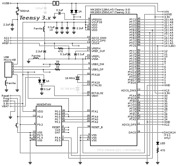
I don't agree, sorry. The USB portion of the chip is powered by the VOUT3.3V pin, see the schematic
schematic3.gif

and page 112, 113, 115 (among others) in the K20 manual https://www.pjrc.com/teensy/K20P64M50SF0RM.pdf

I found that out the hard way - on a custom board I had made, the K20 enjoyed a external power supply (3.3V) supplying all four VDD pins but I left out Vout3.3 because I thought it was solely related to the voltage regulator (which I was not using). Paul and others noticed my error when I reported a 'dead' teensy derivative (or whatever you want to call a homemade teensy).

To fix the issue, I got to enjoy lifting a single K20 pin off the PCB (i.e. Vout33, chip pin 7), attaching a tiny single strand of copper wire to it, and then running the copper wire to a VDD pin to feed the VOUT pin with 3.3V. This was not easy. I do not recommend it for fun, even if you have the right equipment and better eyes/hands/soldering skills than I.

The VIN pin can be left floating and the Teensy will function as long as you supply the Teensy 3.3V pins with appropriate power. Whether you do this with an external power supply (aka wall wart) or an external voltage regulator modifying a variety of 5V sources (for example) to make a regulated 3.3V power source is immaterial.

If there is one thing I would have considered doing differently re: the Teensy schematic, it is the use of the single-cathode, dual anode Schottky diode supplying Vregin from VIN. If it were me, I would have configured it such that VIN and VUSB would feed one anode leg each instead of VIN feeding both. That way, it would be even simpler to supply a teensy with two sources of power. But I am sure Paul had his reasons for designing it the way he did. My guess is that he needed both legs of the SOT23 Schottky to carry enough USB or VIN current alone and two separate 200-mA capable schottkys likely would have taken up too much board space.

The teensy board is a miracle re: capacity vs. size as it is. So no criticism here re: the Teensy board design - Paul is light years ahead of where I will ever be and I am sure he had his reasons for designing it the way he did.
 
Last edited:
You may be correct, but Ive seen ldo blow up with having power on the output an not on the input(may not be the case with the k20 as it may have protection)

Section 6.8.3 USB VREG electrical specifications (in the K20P64M72SF1 datasheet) indicates, but does not catagorically state that power is derived from the vregin. I dont disagree with you that the usb module is powered from the vregout just wouldn't hedge my bets that it wont potentially damafe the k20.
 
You may be correct, but Ive seen ldo blow up with having power on the output an not on the input(may not be the case with the k20 as it may have protection)

Yup, that's why my initial design didn't power Vout33... I had no idea that the USB bus depended on power from that pin. Reading through the K20 literature, the design choice makes more sense, i.e. it appears that the designers wanted to give application engineers maximum flexibility, including the ability to shut off power to the USB portion of the chip while running battery power (3.6V) directly into the VDD pins (aka 3.3v) and allowing operation down to 1.8V (though presumably at lower frequencies and all that).

As for damage to the LDO, as long as the damage stays local (i.e. just blows up the LDO), I wouldn't care, I don't use it anyway. But based on the info inside the manual (i.e. the recommendation to leave the Vreg and Vout33 floating whenever USB is not in use), I may redesign my boards (yet again, sigh!) to enable VRegIn and then use the Vout33 with just the USB bus. But for the time being, I'm going to leave the units as is, since they seem to work just fine.
 
Yeah, I know the feeling. If only PCB and circuit designs where easy to fix and re-fabricate. Right! Time to invent a 3d PCB Printer that has multi layer, plated through hole and ENIG finishing and cost under $1k, sigh! one can only dream!
 
You may be correct, but Ive seen ldo blow up with having power on the output an not on the input(may not be the case with the k20 as it may have protection)

Does this mean it would be unsafe to connect a 3.3V supply to the 3.3V pin? I cut the VIN-USB trace, and connected 3.3V to the 3.3V pin. It seems to work just fine with the USB connected.

Eric
 
Personally I would put 3.3v on VIN not the 3.3v pin. The Internal LDO on rhe K20 goes into bypass mode on anything less than 3.6v so you will see it come out on the 3.3v pin. In effect keeping everything happy and powered.
 
Some blurb from a LDO manufacture "Reverse-Current Protection Feature: A typical LDO with a PMOS pass device has an intrinsic body diode between VIN and VOUT. When VIN is greater than VOUT, this diode is reverse-biased. If VOUT is greater than VIN, the intrinsic diode becomes forward-biased and conducts current from VOUT to VIN, potentially causing destructive power dissipation. Some LDOs, such as the ADP1740/ADP1741, have additional circuitry to protect against reverse current flow from VOUT to VIN. The reverse current protection circuitry detects when VOUT is greater than VIN and reverses the direction of the intrinsic diode connection, reverse-biasing the diode."
 
Personally I would put 3.3v on VIN not the 3.3v pin. The Internal LDO on rhe K20 goes into bypass mode on anything less than 3.6v so you will see it come out on the 3.3v pin. In effect keeping everything happy and powered.


I apologize for resurrecting this thread, but I'm still not entirely sure what the situation is.

When I connect 3.25v regulated to Vin on the teensy, I see ~2.95V on the 3V3 pins. This makes sense to me insofar as someone say there's a 0.3V drop diode somewhere.

But this sounds like connecting my regulated 3v3 to Vin versus connecting it to a 3V3 pin, is very different.

Not wanting to risk my teensy [by testing what would happen if I connected 3v3 to the 3v3 pins instead of Vin], but still being a little confused, I hoped someone could help clarify. Thanks.
 
That's correct, On a teensy there is a Dual diode between the VIN pin and the processors LDO VIN. This diode will have a voltage drop of about 0.3v. The statement I made was from experience on powering a custom board and how I would not leave the VIN unpowered. I forgot about this diode drop.
 
Ah, thanks.

So i guess part of my confusion is because the conclusion is that one could power the teensy with 3v3 to Vin or with 3v3 to the 3.3v pin, either works. The difference is that the Vin pin has some polarity protection via the schottky, and the voltage to the MCU would be 3.3V - Schottky Drop.


What isn't clear to me is whether I could power both Vin and the 3.3V pins with 3V3, or if that would cause a power issue. I think I'd like to power via 3.3V pins so the MCU can get 3.3V not (3.3V-0.3V), but I also need the USB module to work.
 
Sorry don't know the answer to that. It depends how the MCU's LDO is wired up. The worse that can happen is that the MCU's LDO blows up and you would have to supply 3v3 externally forever. But these chips are resilient little beasts.

I accidently solders one backwards, it was a long day and I didn't match the dot on the chip with the dot on the board. I noticed this issue after several hours trying to figure out why the board wasn't working.
Re positioned the chip, and it worked fine afterwards, was actually amazed.
 
Status
Not open for further replies.
Back
Top