Detect USB connected

Status
Not open for further replies.

turtle9er

Well-known member
Hi,

I have a battery powered device that enters sleep mode after an initial calibration routine. It then comes out of sleep when data collection begins with a push of a button. Upon completion of collection, it enters sleep again. I am doing this since this project is going to people to use and worried they might forget to turn it off and will drain the batteries (population is +60 that have had strokes), so changing batteries etc is not ideal. So, my problem is that another lab is in charge of the device and before sending it home with the subject they need to get calibration values via the serial port and also update the code for each subject. With it going to sleep, I lose the usb connection. I can upload the code by pushing the button on the device, but would rather make it easier for the other people....so a short story long, is there a way to indicate that the USB is plugged in (meaning they need to update code and don't want it to sleep). I was thinking of just reading VUSB, but it can be over 5V and could use a simple resistor divider (what is digital pin high low levels?), however wondering if there is some other code that I can use to indicate usb is connected.
Sorry for the rambling, just wanted to explain reason for why I want it to work this way. Any help or suggestions would be appreciated.
 
Does anybody see an issue with reading the VUSB straight into a digital pin? Will this cause issues with the usb port at all, ie: power surge on the port? Also, what is the minimal signal level that will record a HIGH level on the digital pin in case I need a to implement a voltage divider to prevent frying the digital pin. VUSB measures 5.16V when plugged into my laptop, however this will be used on other computers and not sure how high or low VUSB might be.
If anybody knows of another method programmatically, i'd love to hear from you.
I would not. If that digital pin gets programmed as an OUTPUT then set to 0, you may zap that I/O bit or worse.
The Teensy 3.1 digital pins are (all?) 5V tolerant, and I suppose that means up to 5.16 or more V? better read the spec.
USB 5V is notoriously flaky. So you probably need the pair of resistors. With just one resistor from pin to VUSB, the pill will be floating/indeterminate unless the K20 chip has a pull-down capability.


Can you also detect USB connected by Teensy3 software looking at the Teensy status to see if the host PC has enumerated the device?
 
Does anybody see an issue with reading the VUSB straight into a digital pin?[/QUOTE
Well, putting VUSB on a digital just give a "0" or a "1" in my opinion, digital pins can handle 5V,


VUSB measures 5.16V when plugged into my laptop, however this will be used on other computers and not sure how high or low VUSB might be.
In that case, a ADC is needed, and the use of a simple voltage divider to read the max voltage of 5V. My laptop gives me 5.10V, my other laptop give me 4.96V. It's not the same on each and every laptop. To play it save, just asume that the max voltage is 5.5V. I think you need a voltage divider with a range between 0-3V (3.3max).

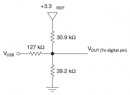
maybe something like this works?
Example.png

Using this 'levelshifter' Any usb connection up to atleast 5.5V is safe... These resistor values can be adjusted to set the max output and the min output... Just try LtSpice for simulations. (I have used this method for level shifting in my project).
 
Last edited:
Well I hope once I program it, then it will be set as input, so not worried about that.
I was hoping there would be another way, like you mention. Maybe somebody has the answer out there. It is not the end of the world, would just be nice since right now it goes to sleep at the end of the setup loop, meaning you have to push the reprogram button. Which brings up another question. If you push the reprogram button, does the correct COM port have to be selected in the arduino IDE, or if I compile the file and push the button, it will upload no matter what. If that is the case, then it should not be that hard for these people to push that button....assuming they don't break the button.
 
That shouldn't be too great an issue, digital pins on the teensy 3.x are 5V tolerant with at least a little headroom there.

Personally I'd set up a 2/3rds voltage divider from VUSB to the pin I intended to attach a 'waking' interrupt to and then poll that while awake and go back to sleep when that wasn't high for the period of time I set. (5/3)*2=3.33333' and by using this your device should wake safely on VUSB being present with potential anywhere from 3.4V to 7.5V - the likelihood of a value much below 4.5V, or above 5.5V isn't that great.


Oddly enough I've found so many digital devices happen to report IO pins as high when they have voltage => 2/3rds of their VCC and low when <= 1/3rd that I tend towards liking 3rds :)
 
Last edited:
If you push the reprogram button, does the correct COM port have to be selected in the arduino IDE, or if I compile the file and push the button, it will upload no matter what. If that is the case, then it should not be that hard for these people to push that button....assuming they don't break the button.

I switch from ports often on my laptop, but i dont set the com port in the Arduino IDE, it switch automatically here... Don't know if that happens on every laptop?
The hex file is loaded into Teensy application tho? It will upload anyway, atleast, i havent interfaced any problems with that....
 
Chopsticks: What is the 3.3V and resistor doing in your schematic and how does it differ from a straight up voltage divider?
For my design I already have 33k and 68k resistors, so I could just add 2 more to my board to create a divider, and it should give me a high value every time since it will be above 3.3V. Thanks for everyones input.
 
The 3.3V is the teensy's 3.3V output. With this divider, a range can be set from a certain voltage. Basically, the level shifter is a three-resistor voltage divider, where R2(30.9k) and R3(39.2k) forms a voltage divider from 3V3 input. This can be seen as a voltage between the 3V3 input and ground with specific impedance. The output voltage can be calculated by the Norton-Thevenin methods. Also usefull for negative voltages. it actually doesnt matter how high your voltage is, the max won't be higher then 3.3V tho, i only tested it with -10 and +10V. the range is then between 1V and 3V
 
Last edited:
@Chopsticks: imho that treatment of the voltage from VUSB is not only overkill but also potentially unreliable, in the task specified by turtle9er, pending the exact values of resistors used in the finalisation of your design.

I do not know why you mentioned ADC earlier as turtle9er only asked about sensing that USB is connected and didn't specify intention to read that voltage, aside from high or low, for any use in their project.

@turtle9er: If you dig into the datasheet(s) for MK20DX256VLH7 (or significant other in this series) I expect you will find that minimum value required to read as 'high' is very close to => 2/3rds of VCC and values below that will be treated as low - I also expect that if you kept digging you should find a flag in some register relating to USB to indicate that data lines are present; meaning that you could sense it programmatically with no wire/resistors between VUSB and a digital IO pin on the device.
 
Yes it will program when you push the "Program" button on the teensy while in sleep mode. What sleep mode are you going in? You really don't need to worry about usb in this case, just make sure the USB is plugged in. When sleeping the USB won't show up in ardunio ide or anywhere but the teensy loader will see it once you hit the program button.
 
also even if you wake from sleep and have wait loop for someone to program it you still have to hit the program button. Currently this is the only way to program the teensy after going to sleep.
 
I am just using sleep mode, right now it enters after the setup loop, just incase the participants turn it on and forget, so it will reduce battery drain. I just wanted to set it up so if the USB is connected, then it would not enter sleep right away, meaning you could just hit upload and the file would change. The other method of hitting the reprogram button works, but for the people that will be using this device, the simpler the better. If I can tell them to plug in the usb, turn it on, and then upload the code, then I think that will be the easiest for them. I will take a look at the datasheets and see if there is some sort of flag set when usb is plugged in.....however I am not sure if I could figure out how to use this with a register reading. Thanks again for your help.
 
Yes I am using that library. I sleep after setup and upon a button press, it wakes up, records data...then on next button press it stops recording, saves file, then sleeps again. So right now, if they want to reprogram the teensy, they loose the serial port since it sleeps right away, meaning they have to compile the program, then push the reprogram button (which might be more confusing for them).
 
is this in a enclouser? If so you could bring out a button that connects to program pin on the teensy. If not why not hold off on going into sleep mode for a certain amout of time. Setup some timer that goes to sleep when it times out. You could even log user activity and reset that timer if it currently being used. But that being said once it does go to sleep then they will have to push the onboard program button or one that you could bring out.

Another option is to use the CPU function "LP.CPU(TWO_MHZ);" which basically just slows the clocks down to save power. There are five speeds
  1. TWO_MHZ
  2. FOUR_MHZ
  3. EIGHT_MHZ
  4. SIXTEEN_MHZ
  5. F_CPU - this is whatever you programed as
The USB is not active while running below 24MHZ and they will have to hit the program button if running at a slower speed but it will program when you call "LP.CPU(F_CPU);", basically running the teensy cpu at "full speed". What you could do like said before is put a voltage divider from the VUSB pin to a digital pin and attach a interrupt to it. In that interrupt fuction call the LP.CPU(F_CPU).
 
Thanks for the reply duff...it is in an enclosure, but they have to open it to get to the usb due to build constrains. So they could push the button. I think my next step will be to meet with the people that will use the device. If they understand the process of just pushing the button after trying to upload the code (get the error msg on the arduino ide) then I will go that way. If not, I will use a voltage divider to detect VUSB, if present, don't go to sleep, if no VUSB, then sleep as usual. My previous method was using elapsed time to measure no recording for 5 minutes, it would then go to sleep, but then thought I could really increase battery life if I could sleep during recordings. Might just use your method...sleep after recording, or sleep after 5 minutes....then at least it only runs at 36mA for 5 minutes, which won't be that bad. Thanks again.
 
Think I might of figured it out. Looked through the manual and found a USB status flag. I then just looked at the lowpower module.c example and changed it a bit to work. This is the code i used. If is set it to 0x00, it prints 'worky', if I put 0x01, it does not print. I have not clue how it works.........but it does.
#define BITBAND_ADDR(reg, bit) (((uint32_t)&(reg) - 0x40000000) * 32 + (bit) * 4 + 0x42000000)
#define BITBAND_U32(reg, bit) (*(volatile uint32_t *)BITBAND_ADDR((reg), (bit)))
#define BITBAND_U8(reg, bit) (*(volatile uint8_t *)BITBAND_ADDR((reg), (bit)))
#define USB0_OTGSTAT_ID 0x07

void setup() { }

// the loop routine runs over and over again forever:
void loop() {
if ((BITBAND_U32(SIM_SCGC4, USB0_OTGSTAT_ID)) == 0x00)Serial.println("Worky");
delay(1000); // wait for a second
}
 
#define USB0_OTGSTAT_ID 0x07
}

that bit is for I2C1 (Teensy3.1) and Reserved for (Teensy3.0), you want 0x12.

Code:
void setup() { 


}


// the loop routine runs over and over again forever:
void loop() {
  if ((BITBAND_U32(SIM_SCGC4, USB0_OTGSTAT_ID)) == 0x00)Serial.println("Worky");
  delay(1000); // wait fora second
}
All this tells you is that the usb clock is on or off, it does not tell you if you have the usb connected.

Also your description on the this project is pretty thin, what does this thing do?
 
This project is for another lab that wants to have subjects (who have had a stroke) to do exercises that involve wrist extension. In the past they have done similar projects, but they have no way of monitoring the actual effort during their exercise, other than them keeping a log of the exercise they have done. So I have created a device with a cheap load cell to measure the amount of wrist extension. So this device will be sent home with the subject to do 2-3 weeks of exercise, using the device 3-5 times day for 5-10 minutes each time. My worry is they will forget to turn it off, burning through the batteries, and then not being able to replace the batteries etc. So I thought I would implement the low power library to make sure that during collection it is at least using very little power, therefore making sure the batteries will last the full 2-3weeks. This is just a safety measure. The issue is, the people in the lab will have to 1) calibrate the device before sending it home with the subject and 2) changing the file so it uses a unique file name for that subject........So, I was just worried that if it goes to sleep right away, they might get confused how to upload the code (I know it is not that confusing, but an extra button push is something I could try to eliminate). I thought I downloaded the 3.1 manual, and that is what I saw for OTGSTAT. I have no clue about any of this...just reversed engineered something, and I yes it does not work, jumped the gun on that one. I was looking at page 981 in the manual....if you can direct me in the correct direction that would be great since I do want to actually learn what makes it work. Thanks again
 
@turtle9er: Please consider breaking long blocks of text up into paragraphs to provide white space which goes further to assisting people to read it than many people think - I am interested enough in what you are doing to read it but I got to 1st full-stop and decided to TL;DR it because my eyes were starting to swim in the text where it isn't really all that long in the scheme of things.

@duff: been considering, since your second post in this thread, to ask you if you would check out how difficult it would be for you to implement a wake-on-USB connect into your low power library because I would be stunned to study relevant related documents from Freescale and find that there is no interrupt basically driven by the action of connecting the USB (having set it up in registers etc, of course) - may be related to USBDCD but that may just as well be a red herring.
 
Thanks Rob.....I was thinking that this morning when I was rambling on another post. I type like I think, which is erratic.

Plus free beer/wings night school does not help.
 
i agree on how the format of your questions gets you better results.

i looked into the USB wake thing a while back and couldn't come up with stable solution. In "DeepSleep" or "Hibernate" i don't know of any way to wake except for monitoring VUSB on one of the pins. USB is not one of the wake modules in those modes. In "Sleep" though, any interrupt should wake it but I choose to disable the USB because I had my computer do funny things when i tried to open a serial monitor while in that sleep mode. Arduino IDE would freeze or I had my computer crash a few times.

When i get some time i will reinvestigate this but i don't know off hand if any interrupts are generated when plugging in the USB. My guess would be probably?
 
USBDCD was the nearest potentially usable thing I found by quick skimming but whether the relationship with charging cells can be dismissed and the interrupt(s?) it can generate can be utilised for the purpose of waking from something like 'DeepSleep' I can't be sure of, pretty cool if you manage it but there is always the VUSB sense proposition anyway.

@turtle9er: You are welcome, actually, yours may be the best response I've seen to similar advice in a forum ever - good on you!
 
Am i chasing my tail looking at the OTG status stuff on page 975 and on. I have been playing around and can read the bits, but they don't change.

Also, looking at the mk20dx128.h file, those status registers are there, but they don't seem to match the manual...I assume if it is 8 bit and the field value is 7, then you use 0x07, but in that file is usually has 0x80.

I am just going off the low power stuff, since what is defined matches the manual.
 
Status
Not open for further replies.
Back
Top