Which IC gets fried?

Status
Not open for further replies.

keeb

Member
Ironically, while trying to find a USB cable to cut the +V wire on in order to safely power my Teensy3.1 externally, I somehow fried it. I have my usual go-to cable that I always use, but I was looking for one to slice up, so I was trying a few that I had to make sure I could program the teensy with it.

Just the facts, ma'am:
I was uploading the teensy blink example and tried one cable that didn't appear to allow me to program with it. So I tried another and was able to get the blink to work. Then I tried a third cable...nothing. After that, nothing works. It won't show up as USB device (Win7 64) no matter how I power it. I tried powering up with my known good usb cord only and also by cutting the trace and powering externally from alkalines regulated down to 5v. Never could get it to show up in windows or run the blink program that was the last successfully loaded program. The mysterious part to me is that no components or external power were connected to the teensy at the time of death, so either one of the usb cables is wired in reverse, maybe, (seems unlikely) or it was just the teensy's time to die. This was an OSHpark version that I had just started using the night before to play around with the SDfat and tinyGPS++ libraries. It was working just fine for probably 5 or 6 hours of use total up to the point it died. As far as I know I never really stressed it as far as current goes, as I never had the sd card and gps modules connected to the teensy at the same time, and it should be able to handle them both together anyways. One thing of note is that I did have the arduino ide set to overclock at 120Mhz as I had previously been trying to see if overclocking changed my SD read/write speeds at all (it doesn't). Oh yeah, the button works and I can get 3.3v regulated output when powered.

I'm not exactly concerned with how it died, although I am curious. I'm more interested in whether the Mini54 IC or the freescale IC is usually the one that fries in power related teensy deaths. I'm going to try to resurrect the teensy by attempting to replace the most likely victim first. I'm hoping it is the freescale chip, cause that mini54 is so blasted small I seriously doubt I could replace it successfully with my equipment.

As a side, it is my understanding that since the bootloader is external to the uController, I should be able to drop a fresh MK20x256vlh7 in without having to do anything to it beforehand or..umm..afterhand. Right?
 
can you clarify;
... Oh yeah, the button works and I can get 3.3v regulated output when powered. ...

Do you mean Teensy Loader behaves as if it successfully downloads the sketch to the Teensy?


... As a side, it is my understanding that since the bootloader is external to the uController, I should be able to drop a fresh MK20x256vlh7 in without having to do anything to it beforehand or..umm..afterhand. Right?
Mini54 is pre-programmed by PJRC and can only be replaced by one from PJRC, MK20DX256VLH7 isn't preprogrammed and one from any (reasonable) source should suffice.
 
can you clarify;

Do you mean Teensy Loader behaves as if it successfully downloads the sketch to the Teensy?

I mean the button itself seems to be working fine mechanically when I tested it by measuring continuity between program and gnd. No, the pc never recognizes the teensy at all and the loader never does it's thing.

Like i said, I'm not really trying to figure out if it is actually bricked...I'm just wondering which of the two IC's generally takes the hit in power related teensy deaths. The freescale chip is about $7 bucks (sadly, no samples available) and the mini54 from PJRC is $8, so I'm just trying to make sure I buy the the chip most likely to be damaged and maybe save a few bucks. I'm just interested to see if I can repair it successfully, I suppose.
 
Either one or both ICs can have been damaged, they might have survived and something else on the PCB may be the reason it isn't working any more but there isn't much else there.

You seemed to be saying that the 3.3V from the LDO regulator in the MK20DX256VLH7 is present when you plug the USB cable in so finding out if 'reset' goes low after you press the program button can indicate whether or not the Mini54 is responsive at all; it would be much easier to see with an oscilloscope but If you can attach the GND probe from your multimeter to GND on the Teensy (right over top of USB shell is OK if your alligator clip is big enough, a pin in a GND hole on the PCB is OK provided you can insulate/shield it against touching an adjacent pin) and then hold the tip of the other probe on the reset pin while you press and release the program button your multimeter might update quick enough to show you the reset line 'blink' for a moment.

Reset should be high (~3.3V) while Teensy is running, If reset is always low then either one of the ICs could be what is holding it down and the test I proposed in my last paragraph is useless.

On the other hand; if reset 'blinks' (at least seems to respond to program button press) then there is at least a better chance that it is the MK20DX... which has failed and that seems more likely to me now I come to think of it anyway, although if it was a matter of drawing too much from the LDO reg in the MK20DX... then the 3.3V should be impaired as well; maybe there is more chance that either(/both) IC(s) was destroyed by static shock.


*Note: I've been wrong enough times, especially when working from memory (been a few days since I looked at relevant parts of datasheet(s)...), to make me write something like this note when I see the slightest chance I'm being wrong again - should work out OK, the wronger I am the quicker someone usually chimes in to correct it all :D
 
Great info rob, thanks. My meter is not nearly quick enough to pick up a little blip. It is a super cheap POS. I went ahead and removed the Freescale IC just to see if my ghetto hot air "station" I made would do the trick. So, I'll go ahead and attempt to replace the MK20 and see if that does the trick. Since it is already dead, I'm just gonna chalk it up to to surface mount soldering practice if I can't get it working again. Afterall, for the price of a mini54 and an MK20, I could've just bought a new teensy board.
 
Glad if it really helped, I hope you can get at least faster multimeter if you are gonna play like it sounds you will.

I knew a woman they paid $40(AUD) an hour to work on SMD lines who would use nothing other than a paint stripper (heat gun, fairly aggressive air flow usually) to rework anything with more than about 8 connections - even I can get an SOIC8 with an iron but she beat me hands down in all divisions of rework where I insisted on using the 'proper' work stations electronics companies usually have if they have an SMD dept.

I'd love to see your ghetto hot air station :)
 
I'm just wondering which of the two IC's generally takes the hit in power related teensy deaths.

Usually the MK20. It's far more exposed, with nearly every pin brought out. It's not very tolerant of the 5 volt input spiking above 6 volts.

I'm just interested to see if I can repair it successfully, I suppose.

It's not easy to get so many pins desoldered without damage to the PCB.
 
...

It's not easy to get so many pins desoldered without damage to the PCB.
If you've a pro hot air rework station, appropriate nozzle, only set it a little above the melting point of the solder in use, patience, and you be very gentle in attempts to lift the device while waiting for all connections to become 'mushy' it isn't that hard; I've had to replace (it must be) 1000s of ICs in my time with 4 or 5 electronics companies and practice definitely improves results - I lost all NC pads (no trace coming away from them) on my first attempt with a little damage to some 'important' pads I only just got that PCB working again.

A bigger problem I've found is accidentally blowing away light stuff (resistors, caps, seriously small inductors etc) which are very close to the target IC.

I still lose the odd NC pad here and there if I am even only a little too cavalier with it - bigger risk is use of solder wick to remove old solder, really gotta be careful and gentle with the tip and wick to make nice flat pads to reconnect to if you are going to hand solder and not use extra flux and hot blow back onto the old solder.
 
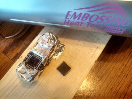
Don't laugh...
... here are the main ingredients to my ghetto hot air "station": a piece of wood to protect the kitchen table, some tinfoil heatsink, and my wife's craft heat gun. I like to think that MacGyver would be proud

IMG_20140701_132936_356.jpg

I've flowed several high power LEDs to MCPCBs using the craft gun, and I figured it would work well enough the other way around. It worked great. The tinfoil was to keep all the other smaller components from reflowing and getting blown around in the process.

I've been soldering stuff for a very long time and I'm fair to decent with an iron, but I've not done much surface mount stuff. I'm debating if I want to use hot air again, or try the iron dragging approach when it comes to replacing the IC. Choices.
 
haha, I like it; oh, you said "Don't laugh" - soz :p

Looks like a bonza job of removal without damage you have done there.

Unless you have a wave-tip for your iron, and you are confident of dragging it across the pads only just contacting the end of each pin on the way past, I recommend not trying to drag the tip for doing up that IC; too easy to bend them into each other and make fairly difficult problems to have to try to fix.
 
It's Alive!!!

Just wanted to update the thread for a little closure... I got a new MK20DX256VLH7 from mouser (sadly, this is one IC that freescale doesn't supply samples of), and was able to successfully replace the dead IC. I used some homemade flux along with a small bevel tip on the iron to drag solder the chip on. The hardest part by far was just trying to get two corners tacked down with everything lined up. I was really wishing for some kapton tape, but I did finally get it lined up. It took me two sides to figure out how little solder was really needed to get all the pins, but then it went pretty smoothly. A little solder wick handled any bridges. Probably not the best package to cut my drag soldering teeth on, but it wasn't really that difficult.

Anywho, I plugged it in, windows recognized it, and I was able to blink an LED. success.
 
I am confused by this thread.

Does the MK20DX256VLH7 require a boot loader from PJRC or not? Or did you buy one from mouser with the PJRC bootloader on it? I don't understand that part of the discussion.

Great job on doing the chip replacement. I have a Sparkfun Heaterizer XL-3000 that I use for rework of large chips. I have not done one with as many pins as the MK20DX256VLH7, but I have upgraded atmega 8u2s to atmega 32u2s on some boards I have.

So +1 for ingenuity!
 
On the teensy3 the boot loader resides on the mini54 IC, so you can replace the freescale microcontroller with another one without having to flash anything. In my case, it appears the only thing damaged was the free scale chip, so I could just drop a new one in and let the mini54 do its thing.
 
Status
Not open for further replies.
Back
Top