Teensy 3.1 Voltage sensing and low battery alert

Status
Not open for further replies.

danb

Member
I just bought the Teensy 3.1 (It's really awesome!) and I'm going to use it in a battery powered (LiPo 1S ~3.7v) application. I want to know what is my battery voltage (to do a rough approximation of it's percentage) and after some research in this forum and others I saw a suggested method of dividing the voltage of the battery to 3v3 max (from the LiPo 4.2v max) and feeding it to one of the analog pins to read.

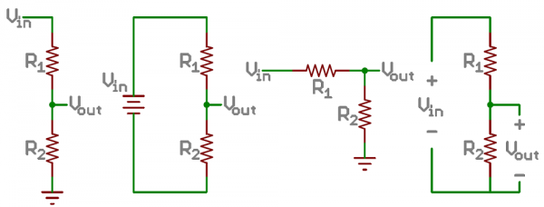
I thought about using R1 = 470R and R2 = 2000R in this voltage divisor circuit (where Vout is the analog pin):
511948ffce395f7f47000000.png
Source: https://learn.sparkfun.com/tutorials/voltage-dividers/all

Though after some thought on it I couldn't fully understand how this should really work because the voltage divider divides the voltage and for 4.2v it indeed outputs 3.3v but for 3v for example (a really empty battery) it outputs 2.43v (for my set of resistors) - what my code should look like to give out the approximation of the battery percentage from reading this analog pin?

Another related thing, can the teensy sense it's about to die (not enough voltage to operate normally) and execute a function if that is case? (sort of a low battery alert / interrupt)

* I know about Fuel Gauges and I'm trying not to use one (I don't want to order any extra parts)
 
I usually have a little slop in my resistor divider as to not exceed the max voltage going into a processor.
But with your stuff, With your resistors: with 4.2V coming in you will have 4.2*2000/(2000+470) = 3.4V which is high so personally I would choose a higher R1...
With my Teensy boards I am assuming at least 3S lipos to use with Robotis serovs, So I am using R1=40K, r2=10K, so my analog pin is seeing 1/5th the battery voltage.

But assuming your values: 3.3V goes to 2.429 volts. If you are using the default 10 bit analog to digital conversion, the code can be real simple:
At 2.429v a analogRead will give you a value of about: 2.429/3.3 * 1024 = 753.
Note: in most cases I do some averaging code, that remembers the last N samples and averages them as to minimize some simple fluctuations in the readings.

With my Hexapod robots, they usually have several different levels of code, depending on things like what I am using to control them.
1) Low power shutoff. The code works pretty simple: If the value returned by analogRead is less than some threshold, shut off the motors...

2) If my robot has some form of sound (or potentially LEDS), I may have additional code that again if the analogRead is below some threshold (higher than the shutdown value, make a sound every so often, like maybe a beep every 5 seconds. Increase the frequency as the voltage drops.

3) If my robot has a display or I am using one of my remote controls with a display, I will often display either the the actual voltage or do some form of battery indicator.
Not hard to convert back to get voltage.

Example if analogRead returns 900, that would imply that the voltage at the analog pin was: 900/1024*3.3 = 2.9V.
which converts back to the battery voltage of: 2.9*(2000+470)/2000 = 3.58V.

As how best to convert this to percentage, I am not sure, I simply do it linearly. That is I assume a range of voltages, like: 3.2 to 4.1 or the like and I fill in the battery indicator linearly. So the 3.58V is maybe something like 42% left... Not sure how accurate this is, but...

Hope that helps
Kurt

Thanks for your informative answer, it does help. I'm going to use your resistor set probably. As for how to convert the voltage to percentage I thought about looking at the battery datasheet and they should provide a graph for the relation between voltage and discharge.
 
Last edited:
The chip has 2 low voltage detect circuits built in. I must confess, this is one of the last few parts of the chip I haven't personally used, so I only know what's in the reference manual and datasheet.

These only detect the main 3.3 volt power, which isn't nearly as good as sensing the battery directly or at the input of the voltage regulator (battery after the series diode).

They're documented in chapter 15, starting on page 297. There are 2, called "LVW" and "LVD", I believe meaning "warning" and "detect". Each is controlled by a single 8 bit register, where 2 of the bits configure the threshold.

In the datasheet (separate from the ref manual), the thresholds are documented as:

Code:
       Low-voltage warning thresholds -- high range  (80 mV hysteresis)
VLVW1H    · Level 1 falling (LVWV=00)               2.62 2.70 2.78 V
VLVW2H    · Level 2 falling (LVWV=01)               2.72 2.80 2.88 V
VLVW3H    · Level 3 falling (LVWV=10)               2.82 2.90 2.98 V
VLVW4H    · Level 4 falling (LVWV=11)               2.92 3.00 3.08 V

       Low-voltage warning thresholds -- low range  (60 mV hysteresis)
VLVW1L    · Level 1 falling (LVWV=00)              1.74 1.80 1.86 V
VLVW2L    · Level 2 falling (LVWV=01)              1.84 1.90 1.96 V
VLVW3L    · Level 3 falling (LVWV=10)              1.94 2.00 2.06 V
VLVW4L    · Level 4 falling (LVWV=11)              2.04 2.10 2.16 V

Even though the datasheet uses the term "warning" and "LVWV" for both, I suspect the "low range" is actually for "LVDV" bits (page 300 in the ref manual). A little experimentation with a variable power supply ought to confirm....

My understanding is you just write to that register to configure the threshold and enable the interrupt. Then in the interrupt routine, write to the ack bit, and do whatever you're going to do when the voltage is falling.

Most peripherals have a clock gate bit in one of the SIM registers. I didn't see one of the low voltage detector. Maybe it's always available? If your code crashes when writing to the register, there's probably some way to enable the peripheral first. This is one of the last bits of the chip I haven't actually used, so I simply don't know from experience yet.
 
It might also be worth mentioning, the MK20 chip can run down to 1.71 volts, with only a couple caveats.

The USB port requires about 3.0 volts (I can't find a confirmed spec, but it's approx 3V) to transmit USB compliant signals. Probably somewhere around 2.0 to 2.5, it'll stop being able to communicate.

The on-chip regulator is not supposed to be used with less than 2.7V input. Obviously it can't create 3.3V output when the input isn't higher than 3.3V... but at some low input, the output might rapidly fall, rather than just tracking slightly below the input voltage. To run at lower voltages, you would need to power directly on the 3.3V pin (which lets you run all the way down to 1.71 volts).

The SPI is rated for up to 25 MBit/sec only if the voltage is over 2.7V. Below 2.7V, the max rated speed is only 12.5 MBit/sec.

Obviously, the digital outputs can only drive their output logic-high voltage to whatever the power supply is. They probably will have reduced current sink and source capability as outputs when the voltage is reduced. If using the ADC or DAC with external reference (the default), the analog scale changes with the power supply. For a stable analog range, you'd want to use the 1.2V internal reference.

Thanks, great info. I just read the chapter in the ref and the relevant part of the datasheet and it seemed promising, as the LVW is exactly what I need, but unfortunately LiPo batteries really shouldn't go below 3v (or they will be damaged) and the highest warning voltage (V lvw4h) is 3v (+-0.8v) which is too dangerous for the battery to trust..

Are you sure the chip doesn't have a simple voltage sensor? I mean this LVD and LVW need to read the voltage somehow.. can't I too? :p

EDIT: I read the whole chapter one more time and it does seem like there isn't a way to read the Vin :/ I guess I'll stick with the voltage divider..
 
Last edited:
Would the ADC's VREF channel have any use here?
Code:
void setup() {
  analogReference(DEFAULT);
  analogReadResolution(12);
  analogReadAveraging(32);
}

void loop() {
  int mv;
  mv = 1195 * 4096 /analogRead(39);
  Serial.println(mv);
  delay(2000);
}
 
Last edited:
Would the ADC's VREF channel have any use here?
Code:
void setup() {
  analogReference(EXTERNAL);
  analogReadResolution(12);
  analogReadAveraging(32);
}

void loop() {
  int mv;
  mv = 1200 * 4096 /analogRead(39);
  Serial.println(mv);
  delay(2000);
}

Not really because I can't supply a constant 4.2v to the VREF
 
Not really because I can't supply a constant 4.2v to the VREF

I assume you mean 1.2v. I'm electronically challenged, but I think the 1.2v internal voltage is maintained by the teensy chip for the ADC. As Paul notes further up in the thread, you'd need to use 1.2v internal reference for a stable analog range.

I've used the equivalent technique on AVR's to monitor battery level.
I actually ment 4.2v : As I understood it from Paul and the Arduino library ref ("Configures the reference voltage used for analog input (i.e. the value used as the top of the input range).") - the VREF is the maximum voltage for the analog pins input and output, so for example inputting anything above 1.2v to the analog pin while using the 1.2v as VREF will result in a maximum reading (1023 in the default 10 bit mode) - I would read 1023 whether the battery is full (4.2v) or whether it's empty (~3.3v), so I guess that's not really helpful. (unless I understood you wrong)

So in order to use the VREF correctly I would have to supply it with a constant 4.2v to measure against.
 
Last edited:
No, the little sketch is measuring a known voltage (VREF ~1.2v, datasheet says 1.195v) on ADC channel 39 against the EXTERNAL reference, i.e., the supply voltage, no analog pins required. The sketch reports the supply voltage in millivolts.

AVR example http://hacking.majenko.co.uk/node/57

Quoting Paul from another post:

PaulStoffregen said:
The pins with both analog and digital functionality (pins 14 to 23) are 5V tolerant, even when operating as analog inputs.

But anything over the reference voltage, which is 3.3V by default but can be configured for 1.2V, will read as the maximum value (1023 in the default 10 bit mode). Applying 3.4 to 5.0 volts to those pins will not damage the chip, but you can't read the voltage other than knowing it's over 3.3V.

Because I use a battery with a range of 3v-4.2v with a teensy whose operating and logic voltage is 3.3v - unlike the arduino (avr) where the operating voltage is 5v, so that analog inputs have a maximum readable input of 5v, and not just tolerable to it like with the teensy, as Paul writes - I won't be able to sense anything above 3.3v (when unfortunately my Vcc is almost always > 3.3v) - no matter what my reference is.

Or at least this is how I understand this.
Thanks for you effort to help :)
 
Last edited:
LiPo batteries really shouldn't go below 3v (or they will be damaged) and the highest warning voltage (V lvw4h) is 3v (+-0.8v) which is too dangerous for the battery to trust.

Are you sure the chip doesn't have a simple voltage sensor? I mean this LVD and LVW need to read the voltage somehow.. can't I too? :p

EDIT: I read the whole chapter one more time and it does seem like there isn't a way to read the Vin :/ I guess I'll stick with the voltage divider..

My final try to convince you that you might be able to use ADC channel 39 to monitor the teensy's supply voltage. The sketch won't monitor your battery voltage or Vin, but it will monitor the teensy's supply voltage (e.g., what you would measure from the teensy's 3.3v pin). So with > 3.7 volts at Vin, the channel-39 sketch should report about 3300 mv. As Vin voltage drops, the channel-39 sketch should report a lower voltage. As Paul notes, if Vin falls below 3.7v the internal voltage regulator might go non-linear near Vin of 2.7v.

Here are some metered reading of various Vin values (millivolts) and what the sketch reports (USB disconnected, so need serial connection to your PC)
Code:
  Vin      sketch
 3936      3280
 3578      3245
 3489      3121
 3165      2830
 3016      2674
 
Last edited:
Following Paul's tangent ... probably should start a new thread on LVD/LVW ...

The chip has 2 low voltage detect circuits built in. I must confess, this is one of the last few parts of the chip I haven't personally used, so I only know what's in the reference manual and datasheet.

These only detect the main 3.3 volt power, which isn't nearly as good as sensing the battery directly or at the input of the voltage regulator (battery after the series diode).

They're documented in chapter 15, starting on page 297. There are 2, called "LVW" and "LVD", I believe meaning "warning" and "detect". Each is controlled by a single 8 bit register, where 2 of the bits configure the threshold.

...
My understanding is you just write to that register to configure the threshold and enable the interrupt. Then in the interrupt routine, write to the ack bit, and do whatever you're going to do when the voltage is falling.

Most peripherals have a clock gate bit in one of the SIM registers. I didn't see one of the low voltage detector. Maybe it's always available? If your code crashes when writing to the register, there's probably some way to enable the peripheral first. This is one of the last bits of the chip I haven't actually used, so I simply don't know from experience yet.

I tried the following little sketch, feeding 2.5v into teeny 3.0 3.3v pin. I didn't seem to get an interrupt (though cnt was sometimes 1 on startup?) Maybe there is a SIM register bit somehwere, or I made some mistake ...

Code:
// low voltage interrupt  ch 15  LVW  LVD
volatile uint32_t cnt;

// low voltage ISR, flag will stay on unless voltage climbs above threshold
void low_voltage_isr(void) {
	digitalWrite(13,HIGH);
	cnt++;
	 PMC_LVDSC2 |= PMC_LVDSC2_LVWACK;  // clear if we can
         PMC_LVDSC1 |= PMC_LVDSC1_LVDACK;
}

void setup() {
  analogReference(EXTERNAL);
  analogReadResolution(12);
  analogReadAveraging(32);
  PMC_LVDSC1 =  PMC_LVDSC1_LVDV(1);  // enable hi v
  PMC_LVDSC2 = PMC_LVDSC2_LVWIE | PMC_LVDSC2_LVWV(3); // 2.92-3.08v
  NVIC_ENABLE_IRQ(IRQ_LOW_VOLTAGE);
  pinMode(13,OUTPUT);
  digitalWrite(13,LOW);
  Serial2.begin(9600);
}

void loop() {
  int mv;
  mv = 1195 * 4096 /analogRead(39);
  Serial2.println(mv);
  Serial2.println(cnt); Serial2.println(PMC_LVDSC2,HEX);
  delay(2000);
  digitalWrite(13,LOW);
}

Edit: later observations:
(1) Ref manual suggests PMC_LVDSC1 must select hi or lo thresholds, so I tried setting it to 1, and i think the result (with 2.5v at 3.3v pin) was continuous reset??
(2) Printing PMC_LVDSC1 in setup() shows reset is enabled (0x10). Ref manual also says LVDRE, the reset bit, is "write once" ... not sure where in the core init it is set, or if it would be dangerous to not set it ?

Edit 2: working. OK the sketch works with LVDSC1 set to 1 (I've edited the code above), AND to get it to work, i had to start the teensy with variable voltage at 3.3v and then as I reduced voltage, ISR fired (LED on), and then as I increased voltage, LED would eventually go off. If i started teensy at 2.5v, it would lock up RESETing, i assume.
 
Last edited:
My final try to convince you that you might be able to use ADC channel 39 to monitor the teensy's supply voltage. The sketch won't monitor your battery voltage or Vin, but it will monitor the teensy's supply voltage (e.g., what you would measure from the teensy's 3.3v pin). So with > 3.7 volts at Vin, the channel-39 sketch should report about 3300 mv. As Vin voltage drops, the channel-39 sketch should report a lower voltage. As Paul notes, if Vin falls below 3.7v the internal voltage regulator might go non-linear near Vin of 2.7v.

Some time ago, I did some experiments using this technique of measuring analogRead(39) to get an indication of the input voltage. Today I spotted another thread about this (LiPo Battery Monitoring Circuit & Code). In this post I share the findings of my experiments in the hope that others find it useful.

Test setup & Method
I used a Teensy 3.0, the Vusb trace is not cut. No external components are attached and the following code is uploaded:
Code:
    analogReference(EXTERNAL);
    analogReadResolution(12);
    analogReadAveraging(32);

    Serial1.begin(9600);
    Serial1.println("Boot!");
    while (1) {
        delay(1000);
        Serial1.print("analogRead: ");Serial1.println(analogRead(39));
    }

Next, I connected a power supply to either the Vin or 3v3 pin, I used an serial->usb converter to obtain the values returned by analogRead(39). The measurements were performed by varying the voltage, writing down the analogRead value and measuring the applied input voltage with a cheap multimeter (readings up to 0.01V, but I'm not so certain about its accuracy).

Measurements
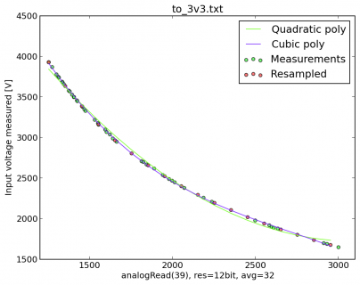
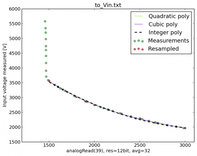
For both applying the input voltage to the Vin pin and 3v3, about 40 measurements are taken. These can be seen in View attachment to_Vin.txt and View attachment to_3v3.txt respectively.

Analysis
The goal is to obtain a function which returns the input voltage applied to the Teensy as a function of the measured analogRead value. To obtain this function I resampled the measurements such that they were equidistant, then I fitted a polynomial through the resampled data points. For the Vin input I also converted the quadratic polynomial to an integer-only version. I used a Python script to analyse the measurements. It uses matplotlib and numpy, the entire script can be downloaded: View attachment analyse.py.txt (.py is not allowed :( ) or Gist.

Input to 3v3 pin:
The polynomial coefficients found are: (leftmost is x^2 and x^3 respectively)
Coefficients P_2: [ 6.24435071e-04 -3.86562880e+00 7.70557029e+03]
Coefficients P_3: [ -3.43172539e-07 2.78848110e-03 -8.24887282e+00 1.05447294e+04]
to_3v3.png

Input to Vin pin:
Coefficients P_2: [ 4.79305738e-04 -3.18084349e+00 7.22111948e+03]
Coefficients P_3: [ -2.31118140e-07 2.03935318e-03 -6.60300979e+00 9.65583352e+03]
I wanted a funtcion without floating point computation so I tried to convert the quadratic polynomial to an integer only version by scaling the positive terms to the maximum allowed in an unsigned 32 bit integer. I assumed the maximum value returned by analogRead is about 3000, this means that a scale factor can be calculated with the positive coefficients of the polynomial. Then the coefficients of the polynomial can be multiplied by this factor, dividing by it after the addition allows computation without floating points:
Code:
Scale: 372346.361704
C0: 178
C1: 1184375
C2: 2688757565
Calculation in C:
uint32_t output = (178*x*x + 2688757565 - 1184375 * x) / 372346; // order is important, negative values need to be prevented.
This integer representation of the polynomial is also plotted in the graph, where it can be seen that this hardly deviates from the floating point values.
to_Vin.png

Evaluation
I used the formula derived above to create a function to run on the Teensy:
Code:
/*
    // be sure to set the ADC to use the external reference, put the following in your setup():
    analogReference(EXTERNAL);
    analogReadResolution(12);
    analogReadAveraging(32); // this one is optional.
*/
uint32_t getInputVoltage(){ // for Teensy 3.0, only valid between 2.0V and 3.5V. Returns in millivolts.
    uint32_t x = analogRead(39);
    return (178*x*x + 2688757565 - 1184375 * x) / 372346;
}
This function returns the input voltage applied to Vin in mV without the use of any external components. I compared the values provided by this function with the readings provided by my multimeter, they were in close agreement. I would be confident in using this to get an indication of the battery level.

The files with measurements and analyse.py script can also be downloaded from a gist: [Teensy] Script used to relate analogRead(39) with input voltage.
 
Last edited:
Hi,

I am currently using the voltage divider method for measuring 3xAA batteries. I tried to use your formula iwanders, however for 3.81V input, I get 3.532 reading. I am using a teensy 3.1, however I assume that should not affect it. Anyways, would of been awesome if I could of just implemented it, save me the time soldering the resistors onto the board.
 
I tried to use your formula iwanders, however for 3.81V input, I get 3.532 reading.
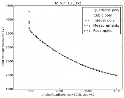
That is to be expected, above about 3.5V, the onboard regulator is capable of maintaining the 3.3V to which the 1.2V internal reference signal is compared (that is what analogRead(39) returns). So if the input voltage is above 3.5V, the analogRead(39) value is always around 1469, which can be seen as the spike of green dots in my graphs around analogRead(39) values of 1500.
The function I proposed is only valid in the range of 2.0V to 3.5V. If the input voltage is higher than 3.5V, it will report a value which is lower than the input voltage. Lower than 2.0V should not really be possible as the Teensy stops working then. I hope this explanation is clear and this voltage range limitation is not problematic for you.

I am using a teensy 3.1, however I assume that should not affect it.
Did some quick measurements on a pristine Teensy 3.1 this morning. Same measurement method. Updated script & datafile on the gist or here: View attachment analyse.py.txtView attachment to_Vin_T3.1.txt.

to_Vin_T3.1.png
The graph is of the same shape, although it seems to be positioned slightly higher.

The obtained function is:
Code:
/*
    // be sure to set the ADC to use the external reference, put the following in your setup():
    analogReference(EXTERNAL);
    analogReadResolution(12);
    analogReadAveraging(32); // this one is optional.
*/
uint32_t getInputVoltage(){ // for Teensy 3.1, only valid between 2.0V and 3.5V. Returns in millivolts.
    uint32_t x = analogRead(39);
    return (178*x*x + 2688743864 - 1182047 * x) / 371794;
}
 
Last edited:
Nice work!
Sadly I get a rating of about 6118 to 6121 as output of getInputVoltage(). It does not matter if I use power over USB or from my 3.7V LiPo. What am I doing wrong?
The analogRead(39) has an output of about 371...
Reading the multimeter, the battery has an output voltage of about 4.1V.
I am using a Teensy 3.1 with some sensors and leds connected, but the pin 39 is just an imaginary pin, isn't it?
 
The most likely problem is with the external reference, be sure to configure the ADC to use the external reference:
Code:
    analogReference(EXTERNAL);
    analogReadResolution(12);
    analogReadAveraging(32); // this one is optional of course.

Perhaps I should place this reference in the code block together with the function. I ran into this myself the other day. Could you let me know if this solves the problem you encountered?
 
Thanks! This worked. I didn't see the connection, but it makes sense.
It would be nice if you can put in the same code block. Much easier to understand for beginners like me :).
 
Nice to hear that someone is using my work and that it's actually working :D.

I put the ADC reference code in a comment next to the function and added the note that it returns the value in millivolts.
 
Yes, it should be possible. In KL26P121M48SF4RM.pdf, on page 87, we can see that VREFH is available as analog channel. On page 91 it is stated that both VREFH and VDDA are available as DAC reference voltages.

This means that using the same technique is definitely possible. I do not yet have a Teensy LC on hand, I intend to do the same measurements and create the function when I have one. Do you require this urgently? Then I might just have to order one... ;)
 
This is great! Any way to do the same thing on a Teensy LC?
The LC doesn't have the same VREF ADC channel that teensy 3* has. There is a bandgap (1.0v) ADC channel and that is what is mapped to channel "39" on the LC in analog.c. So my millivolts sketch looks like the following

Code:
 // compare bandgap channel 39 (hack analog.c AD27) to Vcc   LC
//  datasheet says  1.00  min/max 0.97/1.03 v

void setup() {
  analogReference(DEFAULT);
  analogReadResolution(12);
  analogReadAveraging(32);
  PMC_REGSC |= PMC_REGSC_BGBE;
}

void loop() {
  int mv;
  mv = 1000 * 4096 /analogRead(39);
  Serial.print(analogRead(39)); Serial.print(" ");
  Serial.println(mv);
  delay(2000);
}

Note, you have to enable the bandgap in the sketch.
 
Last edited:
@Manitou, Thanks for jumping in. Did I misinterpret the datasheet? Or is it just that VREFH is not used by default on the Teensy LC? Is there any particular reason this is preferred to the reference voltage as we used on Teensy 3.x?

The bandgap channel you propose should work of course, as long as there's a low - regulated - voltage that can be compared against Vin this method to calculate the input voltage should work.
 
Status
Not open for further replies.
Back
Top