Help needed with DIY teensy please!

Status
Not open for further replies.

mattomatto

Well-known member
Hi all,

I have been developing my own board which is essentially a teensy 3.1 with the audio codec on it as well. In order to keep costs down I have also moved the Mini54, it's decoupling cap and the reset switch to a removable board to only be present when uploading.

I have just finished my first board, plugged it all in, tried to upload code and yep, nothing happens! I could now do with some help to find out why.

First of all, I am measuring power and ground as 3.3v just fine, so the regulator onboard the MK20 is working. The Mini54 also seems to be receiving power ok too. I've checked all my components with multimeter and they look to be soldered perfectly.

Attached is a picture of the board (The missing components are just knobs, LEDs and audio Jacks which do not need to be present), schematics and layout.

Any methods for troubleshooting, suggestions and ideas would be greatly appreciated. I guess the first question is, could there be an issues moving the Mini54 off-board like this?

This is 6 months in the making so I'm determined to get it working. Many thanks!

EDIT: This forum keeps shrinking my images so here are links to schematic/layout:

https://drive.google.com/file/d/0BwUFiZpwTq6WSXJCZmM5Q3B1ejg
https://drive.google.com/file/d/0BwUFiZpwTq6WblM3ZnNfOG40UU0


EDIT:

This is the verbose information I get when uploading:
Code:
23:38:54: remote cmd: "status"
23:38:54: status data sent
23:38:54: remote cmd: "status"
23:38:54: status data sent
23:38:54: remote cmd: "status"
23:38:54: status data sent
23:38:54: remote cmd: "status"
23:38:54: status data sent
23:38:54: remote cmd: "status"
23:38:54: status data sent
23:38:54: remote cmd: "status"
23:38:54: status data sent
23:38:55: remote cmd: "status"
23:38:55: status data sent
23:38:55: remote cmd: "status"
23:38:55: status data sent
23:38:55: remote cmd: "status"
23:38:55: status data sent
23:38:55: remote cmd: "status"
23:38:55: status data sent
23:38:55: remote cmd: "status"
23:38:55: status data sent
23:38:55: remote cmd: "status"
23:38:55: status data sent
23:38:55: remote connection closed
23:39:01: Device came online, code_size = 262144
23:39:01: Board is: Teensy 3.1 (MK20DX256), version 1.03
23:39:01: File "Blink.cpp.hex". 14140 bytes, 5% used
23:39:01: elf size appears to be 262144
23:39:01: elf binary data matches hex file
23:39:01: Code size from .elf file = 262144
23:39:01: begin operation
23:39:01: flash, block=0, bs=1024, auto=1
23:39:01: flash, block=1, bs=1024, auto=1
23:39:01: flash, block=2, bs=1024, auto=1
23:39:01: flash, block=3, bs=1024, auto=1
23:39:01: HID/macos: waiting for device
23:39:01: flash, block=4, bs=1024, auto=1
23:39:01: flash, block=5, bs=1024, auto=1
23:39:01: flash, block=6, bs=1024, auto=1
23:39:01: HID/macos: waiting for device
23:39:01: flash, block=7, bs=1024, auto=1
23:39:01: flash, block=8, bs=1024, auto=1
23:39:01: flash, block=9, bs=1024, auto=1
23:39:01: flash, block=10, bs=1024, auto=1
23:39:01: flash, block=11, bs=1024, auto=1
23:39:01: flash, block=12, bs=1024, auto=1
23:39:01: flash, block=13, bs=1024, auto=1
23:39:01: sending reboot
23:39:01: begin wait_until_offline
23:39:01: HID/macos: status: ok
23:39:02: offline, waited 3
23:39:02: end operation
23:39:02: redraw timer set, image 14 to show for 1200 ms
23:39:02: HID/macos: number of devices found = 0
23:39:02: HID/macos: no devices found (empty set)
23:39:03: redraw, image 9
 
Last edited:
Given how difficult it is to get the pins not to bridge during reflow soldering, I suggest you apply lots of flux and try removing some solder to see if there is a bridge where you can't see it - FWIW, the pins on a MK20 recently looked absolutely fine but the device would not respond. The MK20 was unhappy and was made happy once I removed excess solder.

In another debacle, a reverse-polarity tantalum cap disabled the local power supply (feel free to make fun of me on that one!).

By way of diagnosis, I would also see if the PGM button depress signal is being received by the Mini 54, followed by the Mini54 pulling its reset signal to the MK20 low.

Offboard Mini54's are certainly viable but also somewhat problematic re: ethics since you're asking for support on a product that Paul won't be making any money of other than the initial sale of one Mini54. I use a off-board Mini54 in my design because of space constraints and 2-layer construction but your design seems to be aimed at building a board for which the Mini54 is being used solely as a programming tool / JTAG device.
 
Thanks Constantin. That's good to know you've got it working. I'm going to go over all the pins now to see if I can suck up some solder and will report back.

Ethics-wise, I appreciate your point, however if I get it working I won't be shy about the fact that it's a teensy powered device and I hope to use it to contribute to the library base, so I'm sure there is incentive in there for Paul somewhere!
 
ooh ok, a small amount of progress! The Teensy loader now responds to pressing the program button with 'Done' and 'Reboot OK'. However the MK20 doesn't seem to be doing it's job, can't talk over serial or flash an LED.
 
A word of encouragement about the ethics. I don't speak for Paul, but the success of this project and others like it shows that there's a viable migration path. That's very attractive to any potential customer who dreams big dreams.
 
ooh ok, a small amount of progress! The Teensy loader now responds to pressing the program button with 'Done' and 'Reboot OK'. However the MK20 doesn't seem to be doing it's job, can't talk over serial or flash an LED.

I've run into the same issue - Upload OK but no change of program. It mystifies me as well. I've resorted to changing the revision # in the hello world message during the boot process to ensure that the device actually is running a new program.
 
Hmm that's weird. Have you not got past this point then?

Not consistently, hence the need for the revision reminder that the upload actually happened. No idea why the Teensyduino application would claim a successful upload but the actual program running on the MCU would still appear to be the old one. It's pretty obvious if you try uploading 'blink.ino' vs. 'x.ino', not so obvious if you are stepping through iterations of 'x.ino'.

Incorporating reporting a revision number into the hello world message at the end of the setup() code block affirms that the new code is running. FWIW, the Automatic upload is erratic also, a successful upload usually requires a application of the PGM button. All that suggests to me that I still have a layout/bridging/flux contamination problem or two that is preventing the Teensyduino/CPU from putting the MK20 into receive mode.

Lastly, your schematic is unreadable. I suggest uploading a higher-resolution version for anyone who wants to take a look at it.
 
Last edited:
Not consistently, hence the need for the revision reminder that the upload actually happened. No idea why the Teensyduino application would claim a successful upload but the actual program running on the MCU would still appear to be the old one. It's pretty obvious if you try uploading 'blink.ino' vs. 'x.ino', not so obvious if you are stepping through iterations of 'x.ino'.

Incorporating reporting a revision number into the hello world message at the end of the setup() code block affirms that the new code is running. FWIW, the Automatic upload is erratic also, a successful upload usually requires a application of the PGM button. All that suggests to me that I still have a layout/bridging/flux contamination problem or two that is preventing the Teensyduino/CPU from putting the MK20 into receive mode. .

So it might work one time and then not the next? How frustrating. Although I've tried probably 30 times now with various sketches and not one is working. It's like the USB isn't communicating with the MK20 at all.


Lastly, your schematic is unreadable. I suggest uploading a higher-resolution version for anyone who wants to take a look at it.
The forum kept converting them to low-res jpegs for some reason. Added links to larger files - thanks.
 
I've now built a second unit and it has the exact same behaviour, so I'm confident it is a design issue rather than soldering problems.

Teensy verbose output looks normal, but the MK20 just isn't running the program and doesn't show up as a serial port.

All power pins are showing correct voltage.. no shorts... schematic seems fine... all decoupling caps are close to MK20 and laid out correctly...

If anyone has the expertise and time to take a look at my layout & schematic I'd be really grateful.

Thanks
 
I took a look at the schematic and assuming your pin designations are correct for the given components, they seem to be correct.

I'd confirm that the Mini54 is actually working. From the sounds of it, your Mini54 may not be - the MK20 is responding (USB and all that) but all may be silent on the I2C bus, Reset line, and so on.

Have you kept your I2C bus short? It doesn't like long lengths and interference / crosstalk may be an issue. Have you used a scope to see if anything is triggered on the PTA pins, Reset, and I2C during an upload?

I'd even consider disabling I2C connection to the Audio chip in case its I2C is interfering with the Mini54 somehow (similar I2C bus address?, for example). Pauls teensy design does not feature external pullups on the I2C lines with 2.2k resistors so I wonder if 2.2k is too aggressive and may somehow interfere with the upload process when the Teensy and mini54 are communicating.

For all I know, that may be my issue also.
 
Thanks a lot Constantin. My second board just has the MK20, Mini54 and supporting components. I'll have a look at all connections on my scope and report back.

All lines between the Mini54 and MK20 are max 7cm long.
 
Ok, here's what I've got:

No activity on I2C SDA or SCL. No activity of PTA2 or PTA3. PTA 0 has constant activity and can see action when uploading.

No activity on reset pin.

So I guess that means that the mini54 is indeed not working? It's power connections seem ok and it has just the one cap attached to it for the LDO. I'll double check the layout for it and make up a new one (Glad I ordered 4 of each board...) and see what I can get.


Cheers
 
Don't discount the possibility of bridging below the pins of the Mini54 where you can't see it, ditto on the MK20.

I'd multimeter it out, i.e. confirm that the connections are good and that you don't have any shorts between pins by accident. Your connector makes it easy to test.

If it's the solder under the chip, try applying flux, some braid and sucking up some solder by tapping each pin with a fine soldering iron.
 
Right, I've made my third of each board. None of them have had any issues with the multimeter. I've been generous with flux and run over all the pins a second time on each. I'm 99% confident there is no issue with soldering. I've double checked all the my schematics with Paul's and that all looks fine. Double checked layout and can't see any problems there either.

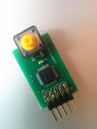
I've attached a picture of the 'programmer' board so you can see how simple it is. The bottom layer is a ground plane with a few traces running through it. The capacitor is a 0.1uF ceramic 0805.

So I'm simply attaching 3.3v and GND to this board and pressing the program button. I see some activity on P0.7(PTA0) and P0.5(PTA3) when pressing the button, but nothing on the others. Is that correct?
Same behaviour when plugged into the MK20 board.

Pic of board:
IMG_20140726_185215.jpg

Layout:
https://drive.google.com/file/d/0BwUFiZpwTq6WSnZyQm1HbGg4b28

Feeling lost!
 
Last edited:
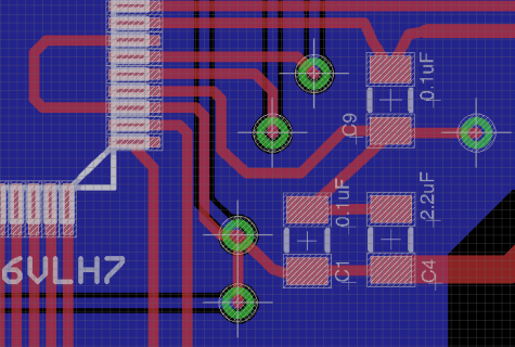
My 3.3v LDO output from the MK20 on pin 7 is going to VDD pin 3 before it goes anywhere else, as shown below. (The loop-back under the chip)

Could this be causing issues?

Screen Shot 2014-07-26 at 20.00.01.png

EDIT: I managed to cut the trace and run it correctly, board still behaves exactly the same :(
 
Last edited:
Something very weird is going on there. Why would the decoupling caps not tie to VDD/VSS directly? For that matter, why isn't the ground plane being used? The layout looks like you let a autorouter do it - if you did, consider redoing it after a look at a book re: pcb design, esp. with a focus on gridded VDD lines, grounding, and so on.
 
Something very weird is going on there. Why would the decoupling caps not tie to VDD/VSS directly? For that matter, why isn't the ground plane being used? The layout looks like you let a autorouter do it - if you did, consider redoing it after a look at a book re: pcb design, esp. with a focus on gridded VDD lines, grounding, and so on.

The other decoupling caps do tie directly to vcc and vdd. But I admit that bit looks a bit weird. I didn't use an auto router. The ground plane is being used, I'm just sending 3 caps to the same via. The schematic shows 3 0.1uF caps which I've put by each vdd pin, but also a 2.2uF cap, which I just out by pin 3, is that correct?

I guess I'll have to design a new board, but I very much doubt fixing this bit of layout would suddenly make it work
 
Looked over your Gerber for the Mini 54, don't understand a couple of things.

1) Why the many vias? Nothing good comes from popping up and down with high speed signals. I avoid vias as much as I can, usually have a continuous ground plane on one side as a result. In other words, I'd consider redesigning that header to make routing conflicts a thing of the past.
2) The ground plane does not seem to be used on one side. That's not helpful. Every time you cut a ground plane, your high-speed data connection currents have to find their way around these cuts, leading to potential interference issues. See Henry Ott's work. among others re: improvement opportunities. IMO, all empty board space should be poured with a ground plane that is stitched to the ground on the other side with multiple vias.
3) The power pins on the Mini54 are missing their de-coupling caps. That's a big no-no. At minimum, there should be a 0.1uF de-coupling cap there, ideally "upstream" from the power pin relative to the power supply.
4) You are using vias where they are not needed, such as the PGM pin.

So I'd redesign your programmer with more attention paid to getting alignment between header pins and Mini-54 pins, ground planes, and no vias other than for GND, if possible.
 
Last edited:
Your larger board would also benefit from a ground plane under the analog side of the business. Again, see Henry Ott, et al for ideas on how to do this without letting digital noise into your analog circuits.

I would also consider a separate analog power supply for the pots. Something like the ADP150 series from Analog. I would use this to feed into the AREF on the Teensy 3.1 and use the external VREF setting in software.

I don't understand the crystal choice or location. Pauls NX chip is smaller, allows much closer placement to the MCU and hence avoids interference issues.

Etc.

You are likely much better off designing your product with a fully-populated Teensy 3.1 using header pins and worrying only about "your" end of the bargain than going the route you are. If the product is a big success, then consider going the 'bare metal' route for the next iteration. You'll get to market faster with a solution that works, and one that future designs can be measured against. That's what I would do!
 
Last edited:
Woah OK. Well thanks for taking the time constantin, I appreciate it. I have already produced many working prototypes using the teensy and audio sheild and it's the cost difference of making my own circuit that makes the product viable. I've spent a good few hundred on teensy bits to get to this point.

Although i clearly have more to learn, i do know everything you just mentioned, but couldnt make it fit any better on a 2 layer board. I honestly have no idea how to route that board with fewer vias. I didnt include decoupling caps on the mini54 people paul's schematic didnt have them.
I've used that crystal because its cheap and performs the same.

When you say the 'ground plane isn't used on one side' do you mean that I have not filled the top layer with another ground plane? Surely that just means you have to cut through the ground plane constantly which is bad?


I guess I'll go back and design a new board without the pots and try and get a solid 2 layer circuit.
 
@ Constantin
Would you have a link to "Hott's work" ?
sure thing:

Apologies, my spell checker or brain fused the first name initial and last together, it's Henry Ott. I consider his Noise reduction techniques book to be one of the better books I've ever read. Speaking as a manufacturing engineer and not a EE. Maybe his observations are obvious to EE's...

There are other books out there that I've liked also, along with good grounding related articles hosted at most ADC manufacturer's web sites that illustrate how high speed signals return on the ground plane underneath the signal trace even if the low resistance path is much shorter. Google for mixed signal grounding, among other topics.
 
Last edited:
Thanks!
I had come across this before as it was referenced on the eevblog and now remember that the price was a little over my pain level at that time.
But then Amazon offers used versions at greatly discounted pricing ;-)
 
Thanks!
I had come across this before as it was referenced on the eevblog and now remember that the price was a little over my pain level at that time.
But then Amazon offers used versions at greatly discounted pricing ;-)

Yes, which is how I got mine. His web site does offer the gist of much of the book for free, so I'd digest that and then move onto the book, esp. if you worry about interference with external sensors attached with long cables.
 
Status
Not open for further replies.
Back
Top