Mr Karoshi
New member
Hi guys, first post, here goes.
I've been trying to get the Teensy 3.0 working with a GT511C1 fingerprint scanner and having really no luck, to the point where I thought I'd fried it - only to solder on a USB cable and find it worked perfectly with the supplied demo software.
The scanner is here:https://www.sparkfun.com/products/11836
Comes with some example code which compiles fine for the Teensy but I get no response from the other device.
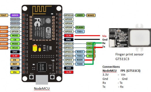
My hardware setup is pretty simple: Pin 1 (scanner Tx) <-> Pin 9 (Teensy Rx), Pin 2 (scanner Rx) <-> Pin 10 (Teensy Tx) and then the 3.3V and GND required are connected to the bottom row of the Teensy by the reset button.
I originally thought that the Serial/UART would need some pull up resistors to 3.3V so tried that, but then read that that's only required for I2C on the Teensy 3, is that correct?
I thought about level conversion but used my o'scope on both devices and found they're both functioning off of 3.3V perfectly fine, I'm assuming obviously that the TTL communication uses 3.3V as Vref and not 5V!
Here is the code I'm using, also pretty basic:
As you can probably tell, it's just blinking the backlight of the GT511C1 and nothing more, yet there is no blinking from the scanner at all, just the power LED with it's steady bright green. I'm also using this library to back the previous code:https://github.com/sparkfun/Fingerprint_Scanner-TTL
As for my platform setup I'm running the Arduino (IDE?) on Mac OSX, but I have Ubuntu and Windows 7 VM's to help with the scanner's demo software.
I've spent literally days trying to sort this and my brain is soup, I'm convinced it's something extremely simple but I need a sounding board, does anyone have any ideas/questions?
Thanks in advance.
I've been trying to get the Teensy 3.0 working with a GT511C1 fingerprint scanner and having really no luck, to the point where I thought I'd fried it - only to solder on a USB cable and find it worked perfectly with the supplied demo software.
The scanner is here:https://www.sparkfun.com/products/11836
Comes with some example code which compiles fine for the Teensy but I get no response from the other device.
My hardware setup is pretty simple: Pin 1 (scanner Tx) <-> Pin 9 (Teensy Rx), Pin 2 (scanner Rx) <-> Pin 10 (Teensy Tx) and then the 3.3V and GND required are connected to the bottom row of the Teensy by the reset button.
I originally thought that the Serial/UART would need some pull up resistors to 3.3V so tried that, but then read that that's only required for I2C on the Teensy 3, is that correct?
I thought about level conversion but used my o'scope on both devices and found they're both functioning off of 3.3V perfectly fine, I'm assuming obviously that the TTL communication uses 3.3V as Vref and not 5V!
Here is the code I'm using, also pretty basic:
Code:
#include "FPS_GT511C3.h"
#include "SoftwareSerial.h"

FPS_GT511C3 fps(9, 10);

void setup()
{
	Serial.begin(9600);
	fps.UseSerialDebug = true; // so you can see the messages in the serial debug screen
	fps.Open();
}


void loop()
{
	// FPS Blink LED Test
	fps.SetLED(true); // turn on the LED inside the fps
	delay(1000);
	fps.SetLED(false);// turn off the LED inside the fps
	delay(1000);
}
As you can probably tell, it's just blinking the backlight of the GT511C1 and nothing more, yet there is no blinking from the scanner at all, just the power LED with it's steady bright green. I'm also using this library to back the previous code:https://github.com/sparkfun/Fingerprint_Scanner-TTL
As for my platform setup I'm running the Arduino (IDE?) on Mac OSX, but I have Ubuntu and Windows 7 VM's to help with the scanner's demo software.
I've spent literally days trying to sort this and my brain is soup, I'm convinced it's something extremely simple but I need a sounding board, does anyone have any ideas/questions?
Thanks in advance.


