Hi everyone,
I am currently getting further and further in to flight sims, and have decided that I need a custom controller. While I have been programming for years I have no electronics knowledge. This is something I am keen to rectify to the extent that I can play around with Arduino/Teensy and similar for fun projects.
My current main flight sim is Il2 Cliffs of Dover, and I am branching out in to DCS world. One of my most immediate controller issues is that I need accurate trim controls. I currently have a CH throttle quadrant which the axes give about 69 degrees of turn? I was thinking of going for some 1, 3 or 5 turn pots.
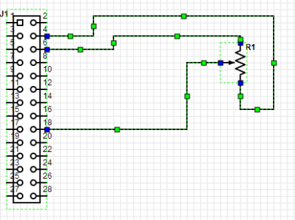
So I bought a Teensy 3.1 and headed down to Jaycar for some parts. End result code is below a very basic diagram.
Pin 4 should be AGND
Pin 6 should be 3.3V
Pin 18 is A4.

My output is this
analog 0 is: 716
analog 0 is: 738
analog 0 is: 758
analog 0 is: 784
analog 0 is: 742
analog 0 is: 736
analog 0 is: 759
analog 0 is: 744
analog 0 is: 741
analog 0 is: 810
analog 0 is: 764
analog 0 is: 713
analog 0 is: 729
analog 0 is: 724
analog 0 is: 747
analog 0 is: 748
analog 0 is: 753
analog 0 is: 728
analog 0 is: 714
analog 0 is: 760
analog 0 is: 759
analog 0 is: 760
analog 0 is: 743
analog 0 is: 715
analog 0 is: 760
analog 0 is: 723
analog 0 is: 754
analog 0 is: 728
analog 0 is: 715
analog 0 is: 804
analog 0 is: 713
analog 0 is: 744
analog 0 is: 737
analog 0 is: 743
analog 0 is: 772
analog 0 is: 750
analog 0 is: 732
analog 0 is: 762
analog 0 is: 737
analog 0 is: 769
analog 0 is: 776
analog 0 is: 722
analog 0 is: 717
analog 0 is: 730
analog 0 is: 765
As you can see values vary wildly. I have been poking around the forums so have tried a few capacitors between the 3.3V and AGND but that makes no difference. I really don't know what I am doing. Can anyone suggest how I should be troubleshooting this?
I am currently getting further and further in to flight sims, and have decided that I need a custom controller. While I have been programming for years I have no electronics knowledge. This is something I am keen to rectify to the extent that I can play around with Arduino/Teensy and similar for fun projects.
My current main flight sim is Il2 Cliffs of Dover, and I am branching out in to DCS world. One of my most immediate controller issues is that I need accurate trim controls. I currently have a CH throttle quadrant which the axes give about 69 degrees of turn? I was thinking of going for some 1, 3 or 5 turn pots.
So I bought a Teensy 3.1 and headed down to Jaycar for some parts. End result code is below a very basic diagram.
Code:
void setup()
{
  Serial.begin(38400);
}

int val;

void loop()
{
  val = analogRead(4);
  Serial.print("analog 0 is: ");
  Serial.println(val);
  delay(250);
}
Pin 4 should be AGND
Pin 6 should be 3.3V
Pin 18 is A4.

My output is this
analog 0 is: 716
analog 0 is: 738
analog 0 is: 758
analog 0 is: 784
analog 0 is: 742
analog 0 is: 736
analog 0 is: 759
analog 0 is: 744
analog 0 is: 741
analog 0 is: 810
analog 0 is: 764
analog 0 is: 713
analog 0 is: 729
analog 0 is: 724
analog 0 is: 747
analog 0 is: 748
analog 0 is: 753
analog 0 is: 728
analog 0 is: 714
analog 0 is: 760
analog 0 is: 759
analog 0 is: 760
analog 0 is: 743
analog 0 is: 715
analog 0 is: 760
analog 0 is: 723
analog 0 is: 754
analog 0 is: 728
analog 0 is: 715
analog 0 is: 804
analog 0 is: 713
analog 0 is: 744
analog 0 is: 737
analog 0 is: 743
analog 0 is: 772
analog 0 is: 750
analog 0 is: 732
analog 0 is: 762
analog 0 is: 737
analog 0 is: 769
analog 0 is: 776
analog 0 is: 722
analog 0 is: 717
analog 0 is: 730
analog 0 is: 765
As you can see values vary wildly. I have been poking around the forums so have tried a few capacitors between the 3.3V and AGND but that makes no difference. I really don't know what I am doing. Can anyone suggest how I should be troubleshooting this?

