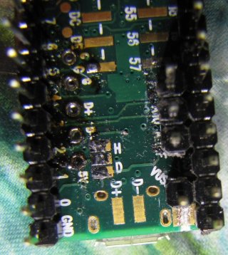
+3.3v Line Shorted to GND

Status
Not open for further replies.

JMeringer

New member
Hello,

Seems my +3.3V line and my GND on my teensy 3.1 have shorted together and are permanently fused. I've ordered another one, but I’m concerned that just assuming "oops, must have just bumped an exposed wire against something bad.... it won't happen again" is just asking for it to happen again.

I'm assuming the possible ways this could have happened are numerous and impossible for someone to identify on a forum post, so instead I figured I'd just ask some general questions about what it would take for this to happen. Then, at least I can rule out possibilities that people are confident are impossible and investigate possibilities that people think might be likely.

I will say however that the board was powered by the USB in parallel with a BEC (battery elimination circuit, regulated 5V) from a brushless speed controller. I never cut the trace between VUSB and VIN because both inputs are a regulated 5 volts. Also, I'm aware of the short because my multimeter reads +0.02V between the +3.3v line and GND when the thing is powered (+4.3v between the VIN and GND) and when unpowered the continuity meter reads "0" (Closed). (I'll include a little more detail at the end in case ppl are interested.)

So, to the questions (but feel free weighting in on whatever you think would do this):

- Can I assume the short is due to damage to the 3.3V regulator? Is there a vulnerable diode in there that if fried would connect 3.3 to GND? The Teensy 3.1 schematic makes it look like the regulator is internal to the microcontroller and not an external component mounted to the board. If that’s the case, it makes testing the regulator difficult (impossible?).

-I should note that never was any smoke, burning, sparks, smells, etc observed so I’m assuming the damage was quick and to a semiconducting device (not heat fusing traces together). I don’t see any diodes on the Teensy 3.1 schematic that if it failed closed would connect the 3.3 with the GND (can a capacitor fail open?). Does anyone know of a component (internal to the uC or external) that if damaged would result in this issue.

- Can the teensy 3.1 +3.3V regulator be damaged by drawing too much current from it? The pin out makes it clear that it is limited to 100mA. I had assumed that if you exceed this amount the device would just act flaky, not damage itself and fuse lines together.

- Could a short to an I/O pin effect the entire 3.3v line? I've read that drawing too much power from (or shorting out) an I/O pin can destroy that pin but not render the entire board useless. Ruling out the I/O pins would greatly narrow the possibilities.

-Can I assume that if there was a short between my +5V line (Vin) and GND that the teensy won’t necessarily be damaged because the current would bypass the uC altogether.

- The highest voltage on the board is +5V, is this even enough if I connected the power backwards to damage anything? I thought I read somewhere that it would take at least 6.0V to start blowing diodes on the teensy.


Just a little more detail incase ppl are wondering....
- my 3.3volt I2C devices seem to work fine.
- My teensy sends out servo and speed controller signals (I'm using it as an autopilot) and I was having issues with the motors starting by themselves and eventually concluded that if they want signal voltages from 3v to 5v and I'm giving them +3.3v, a nosiey signal line might be the cause of the flakey self-starting (more like half starts really).... anyway to correct this I'm using a Sparkfun bi-directional Logic Level Converter (LLC) to convert the 3.3v signals to 5V before going to the servos/ESCs. I bring this up because there might have been a short between one of the high side (5v) signal lines (output) and the LLC's GND.


Anyhow, so to sum up: if you had a teensy and wanted the 3.3v and gnd lines fused but could only use 5.0v and 2 amps (from the BEC) how would you do it?

Thanks
 
Hello,
I will say however that the board was powered by the USB in parallel with a BEC (battery elimination circuit, regulated 5V) from a brushless speed controller. I never cut the trace between VUSB and VIN because both inputs are a regulated 5 volts.
There is a way with two difference power sources that you should apply diodes to prevent backflow through either. I'm not sure where the link is to that page.


- Can I assume the short is due to damage to the 3.3V regulator? Is there a vulnerable diode in there that if fried would connect 3.3 to GND? The Teensy 3.1 schematic makes it look like the regulator is internal to the microcontroller and not an external component mounted to the board. If that’s the case, it makes testing the regulator difficult (impossible?).
I'm not sure how you can be certain, but you're right that the regulator as far as I was recently aware is internal to the chip. There certainly would be a pathway for it to be the culprit, but I'm not sure which. Be aware that the input if I'm not mistaken is limited to 5.5V and a crappy BEC could go above that.

- Can the teensy 3.1 +3.3V regulator be damaged by drawing too much current from it? The pin out makes it clear that it is limited to 100mA. I had assumed that if you exceed this amount the device would just act flaky, not damage itself and fuse lines together.
I do not believe the teensy regulator is current limited, I do think it would die from too much current.

- Could a short to an I/O pin effect the entire 3.3v line? I've read that drawing too much power from (or shorting out) an I/O pin can destroy that pin but not render the entire board useless. Ruling out the I/O pins would greatly narrow the possibilities.
*Based on experience with the AVR chips, a different type* the I/O pins do not typically burn out the entire board, but that there's no guarantee that they won't.

Just a little more detail incase ppl are wondering....
- my 3.3volt I2C devices seem to work fine.
What do you mean by this? I assume your board is dead and so I'm not sure how you know this at this point.


Anyhow, so to sum up: if you had a teensy and wanted the 3.3v and gnd lines fused but could only use 5.0v and 2 amps (from the BEC) how would you do it?
What does this mean? What do you mean by *want* the 3.3v and gnd lines fused.* Do you mean you want there to be a fuse to protect the two lines? I'm not really sure what you mean.


Take my advice with a grain of salt, I'm a newb here, but I thought I'd offer some preliminary response.
 
Same thing – 3.3V shorted to GND

I seem to have the same problem.

I had the thin connectors cut, as the Teensy was being powered from the external 5V source. I needed to flush the software with a new version, and I connected it just to USB. For whatever reason I saw the project come to live, which I wasn't expecting, given that VIN was disconnected from USB. But I guess USB power still went to VIN.

Now I can detect a short between 3.3V and GND, and when a USB cable is plugged into the board, it was pulling 300mA , which seems excessive for Teensy that's not connected anywhere.

I wonder what is the right way to flush Teensy, after the connections have been cut to use the board with an external power supply?

Also, I have two such Teensy boards, fried and all. I am worried I will do this again.

What causes this?

Thanks!

I'm not 100% clear on what happened with your situation, but it sounds like you didn't properly cut the traces. If you cut the traces correctly, it will not power on with usb power. You may have gotten unlucky, and the two power sources damaged the regulator on the chip.

Can you post a photo of the cut traces? It will be hard to properly focus and you will have more luck if you can get a proper camera rather than a smartphone. But if you can only find a smartphone check if it has a "macro" setting to help the focus.
 
As you can see in the schematic:

http://www.pjrc.com/teensy/schematic.html

those 2 pads cut the VUSB power before it can get to the diodes or anywhere on the chip. If the Teensy was able to power up with the USB cable only, something about your connections must be very different than you believe it to be.

Now I can detect a short between 3.3V and GND, and when a USB cable is plugged into the board, it was pulling 300mA , which seems excessive for Teensy that's not connected anywhere.

How are you measuring this? What exactly do you do to "detect a short between 3.3V and GND"?

How are you measuring 300mA?

Details of how the circuit is really connect matter. Probably the very best thing you can do is to recognize that things must be different than you believe they are. You've expressed a lot of conclusions, which are probably quite reasonable, but how do you know they're solid if they're based on an incorrect assumption of how the power lines are really connected?

On another recent thread, someone observed a seemingly similar problem, which turned out to be an issue with the 3.3V regulator on Teensy when a very large capacitor was connected to the power line and GND. Maybe you have something like that? Or maybe some other stuff is wired up that's causing trouble?

We also had a case, long ago, where a 3 terminal switching regulator (a "drop-in replacement" for a 7805) caused havoc if it lacked a capacitor on its input. Its datasheet said the input capacitor was only needed for higher input voltage. But it was wrong. The output capacitance and a not-so-strong power source caused terrible start-up problems, which made it reset itself, and the cycle continued over and over.

Details matter!

I wonder what is the right way to flush Teensy, after the connections have been cut to use the board with an external power supply?

Well, the first step is to disconnect ALL external stuff, so only the USB cable is connected. Reconnect VUSB-VIN, if you've cut it. Check the 5V and 3.3V power. Then run Teensy Loader on your machine and press the button on Teensy. If the hardware is still good, Teensy Loader should recognize the board and let you program new code. The 2 LED blink .hex files might be best to try first.
 
Sorry for bumping up such an old thread, but I ran into the same problem as the OP was experiencing.

The 3.3V output and GND pins of my Teensy 3.2 board are shorted. I "fried" two Teensy boards this way over the weekend. At first I thought it could be a real small solder bridge or such, but after killing the second one the same way, it must be something else. My PC does not recognize the Teensy board when I am plugging the USB cable in.

Do you have any idea what happened with these boards?
 
Another fried board

Hi,

Just chiming in to give my experience from today. I have a Teensy 3.5. I suspect that I have been rough on it, since I am getting up to speed with the technology. I am planning to order a replacement, but am quite nervous since I do not know what I did.

Status: The trace between VIN and VUSB is cut. I tried cutting it, checked the resistance with a meter, cut again, tested, cut. Eventually I measured a high resistance. I was a little worried because I could not see well to know when it was properly cut, and I do not know what is below this area as it is a multilayer board. I disconnected everything except one LED that the program code would flash.

Symptoms: When powered by 3 AA batteries (3.62V measured with a meter) on VIN and GND, nothing happens. I used a jumper to connect VUSB and VIN and connected Teensy to my laptop with USB. Yesterday when I did this, there was a beeping on the computer as it recognized the new hardware and I was able to view serial output in TeensyDuino and load new code. Today, no beeping and Teensyduino could not find any connected device. I disconnected the USB and powered it off of a current-limiting voltage regulator set at 3.3V 70mA connected on the 3.3V pin and GND next to the PROGRAM pin. It stopped providing voltage at 1V because of the current limit setting. In later tests, I ramped the current limit higher, but decided 700mA and about 1.5V was as high as I dared test.

Possible culprits:

* When soldering header onto AREF, I accidentally touched the surface mount component next to it, towards the center of the board. The solder on the surface mount glistened, so it definitely melted briefly. Teensy functioned normally after this, but it could be a delayed failure?

* I was doing a lot of work on the device chassis with the Teensy mounted in it, including drilling, carving with a hobby knife, etc. Perhaps the mechanical shocks were a problem?

* I had a lot of wires hooked up at various times: Pins 24-38 were hooked up to a 7-segment display with 120 ohm resistors. PINs 18, 19, 3.3V and GND were connected to some I2C devices, 9, 10, AREF and AGND were hooked up to an external port, a 3V button battery was connected to Vbat and GND. Loose jumpers were connected to VUSB. I did not test all of the connections, and it is possible I had a short someplace.

* I was not consistently practicing careful static electricity procedures. Would Teensy be sensitive to static electricity? If so, drilling could be a great way to build up some nice charges....

* Teensy was mounted upside down, with just a small 1/32" spacer from the ABS chassis. Could heat buildup be an issue? It was not powered for more than a few minutes at a time, so that seems pretty unlikely.

-- Steven
 

Attachments

  • IMG_3512.jpg
    IMG_3512.jpg
    128.6 KB · Views: 259
The varies electronic failure modes wouldn't give a shorts on the power supply normally, though you are right that drilling has some interesting static and EMI potential that may have overwhelmed the on chip protection. Drill bit may potentially radiate EMI from deep in the motor since it's unlikely to have a true ground being a rotating part.

Looking at the schematic, especially the power components on the top edge.
https://www.pjrc.com/teensy/schematic.html

The more interesting test point is what voltage is present at the 3.3V output when 5V can only rise to 1.5V, and what resistance values you get gnd/5V and gnd 3.3V. Many short circuits only show up when system is powered up but this may be a solder related short, so the question is if it's on the 5V side or the 3.3V side, otherwise you need to test under power and work from the voltages to get some idea on how things are going and where the short/failed component is.
 
I don't know what caused the fried boards, but I see one common element here that can blow low voltage CMOS parts like the processor chip. These parts are rated for somewhere between 3 and 6 volts MAX. Most digital ohm meters use a 9 volt battery. Their leads can put out up to 9 volts when used to measure ohms. The fancy $$$ desktop HP meters will put out over 15 volts in the "ohms" mode. I have personally fried some rather rare and expensive test chips by poking around in an unpowered circuit with an ohm meter while working at Motorola in the IC research group. Test your ohm meter with another digital voltmeter if in doubt. Most CMOS chips have static protection diodes built into them which will blow if exposed to 10 mA or more. The low ohms scale of many meters can source more than this.

To check for shorts, I use a 10K or higher resistor in series with the meter leads and look for readings around 10K. This does reduce the resolution, but may save a chip.
 
Thank you, GremlinWrangler and tubelab.com for the diagnostic advice.

I checked my meter manual, and get max .65mA and max 1.5V while testing resistance. The diode test function uses 1.5V constant and potentially more current, which concerns me since I used diode test mode sometimes thinking it protected the delicate circuits. Anyway, seems like my meter is relatively safe. During my tests, I was careful to maintain proper polarity of the test probe voltage.

Resistances, Teensy completely disconnected except meter:
VUSB->Vin: open.
VUSB-> GND: open
Vin->GND: open
V3.3->GND: 1 ohm
AREF->GND: 469 ohms, so not likely the culprit.
I tested all of the pins relative to ground. Most were open. A few had resistances that looked like pull-up resistors, e.g. 123K on A22. The only low resistances I found were:
AGND .5 ohm
VBat 1 ohm

I checked VBAT -> V3.3. The meter reading oscillated between 0 ohm and open. Maybe that is normal since there is a diode between them, and the meter uses varying voltage depending on the resistance?
I checked V3.3->AGND, 1.6 ohm, so the short seems to be between V3.3 and GND, not between V3.3 and AGND.
I got odd readings from the two inner-row GND pins next to pins 5 and 6, where I had previously installed and then removed headers. The meter here also jumped between .1 ohm and open? That doesn't sound good to me.

Then I connected the Teensy with my current-limiting power supply. (Current is as reported by power supply, less the 80mA that the power supply is using itself. I have not tried to validate the current readings.)
Current limit Vin V3.3 Current
70mA 1.9V .05V 60mA
470mA 2.7V .42V 460mA
670mA 3.1V .57V 660mA
770mA 4.1V .23V 320mA

I fiddled with various relatively-safe settings on the current limit and voltage limit, and found that higher current limit does not make any difference and higher voltage limit gives a lower voltage for V3.3.

Looking at the schematic, most likely culprits seem to be the inner pins where 3.3V is right next to GND or one of the capacitors. Would touching a capacitor with the soldering iron cause the solder to flow under it to create a short?

-- Steven
 
Hey guys, sorry for bumping up this thread, but I was doing a project and it caused the teensy LC to create an internal short circuit on the 3.3V, Vin and GND pin. Do you think not having current limiters in the base of the transistors can cause that ? the transistor is connected like this :

Base: output pin
Collector: RGB strip (5V)
Emettor: ground
 
Yes, not using current limit resistors can kill output pins and/or the transistors. The base-emitter junction of every bipolar transistor behaves like a diode. That means that current will start flowing at about 0.55V and then increase exponentially with the applied voltage (which will be limited to about 0.65V). If you try to feed 3.3V into that, this will be seen like a short circuit by the output pin.

Thus, current limiting resistors are always required when driving bipolar transistors with logic signals. Normally, a drive current of 2mA is more than sufficient to have a standard NPN transistor like the 2N2222 or 2N3904 act as a switch. Thus you take the voltage difference (3.3V from the output pin minus the 0.6V base-emitter voltage) and divide it by the drive current (2mA). Thus you'll get 2.7V / 2mA = 1.35kOhm => Next norm value = 1.5kOhm.
 
Depending on how much current you want to switch, 2mA is nowhere near enough base current. Saturation hFE is usually only in the 10-30 range (otherwise, you have a substantial voltage drop across the transistor), so e.g. for switching 1A to an RGB LED strip, you want 30-100mA base current (a lot more than the Teensy can deliver).

You should be looking at using a logic level mosfet instead (still use a base resistor).
 
It is clear that for switching such loads like 1A, the 2mA are not sufficient. I based my example on small signal transistors like the 2N2222 or the 2N3904...

Using a MosFET will solve the problem. The Gate-Source junction of a MosFET behaves like a capacitor. Thus, you'll need a series resistor to limit the very short charge / discharge current peaks. In that case, the calculation is done by dividing VDD (3.3V) by the maximum current which a pin can source temporarily (Instantaneous maximum current single pin limit (applies to all port pins) = 25mA says the data sheet) = 132Ohm, next norm value 150Ohm.
 
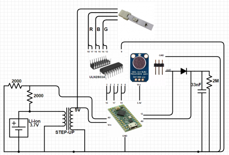
I have a sound-reactive project. The moment I turned my project ON, everything was fine. The moment I played a sound, the RGB strip lit up for only 100ms and the Teensy's CPU got really hot. Something internally got shorted the moment the strip lit up. Now when I test the pins, I detect a short circuit between the 3.3V, Vin and GND pin. It isn't only the output pin that isn't working, it is the whole Teensy LC. The transistor I am using is a transistor array, the ULN2803A (I am using 2 in parallel for each color). I can see it has an Input current of maximum 1.35mA.

I don't know if it is the fact that I didn't limit the current on the base or the boost converter that is feeding my teensy and the strip that fried the teensy.
 
The ULN2803A is a darlington transistor array and not a simple transistor array (being a darlington, you get 2 diode voltage drops vs. 1 with a transistor). It has the necessary base resistors built in, so connecting it directly to Teensy is safe.

Do you have long connecting wires? If so, you could see large voltage spikes.
 
Here is the diagram: let me know if you guys can't understand it. Sorry I know I could have done better, but I didn't have alot of time.
CircuitMic.PNG
 
Same problem here, two Teensy 3.6 are powered from a PSU (SWI25-N 5 volts 4 amps), the USB power jumper is cleanly cuted no flux (checked under the microscope). Two Ethernet modules (WIZ812) are connected to the teensys to transmit the information of 23 encoders + switch (sparkfun COM-10982) in total. So I use internal pull-down for the switches and 46 input for the encoders (pull-up resistance)distributed on both circuits. On one of the circuits is connected 3 TLC5947DAP for controling leds.

Both teensy 3.6 fried (+ 3.3v Line Shorted to GND)! not at the same time, about a week apart.

Question:
Is the 10uF input capacitor (6.3V, X5R (no idea about ESR) from the regulator (CUI, V7803-1500 used for ethernet modules) can affect the Teensy 3.3 volts regulator?

What else!? What a pain in the ass problem. Thank you
 
Status
Not open for further replies.
Back
Top