You are using an out of date browser. It may not display this or other websites correctly.
You should upgrade or use an alternative browser.
You should upgrade or use an alternative browser.
Teensy 3.1 need to output 8mhz clock on digital pin
- Thread starter renasis
- Start date
- Status
- Not open for further replies.
potatotron
Well-known member
Typing this from my work computer, without access to an actual Teensy, but how about something like this:
Code:
IntervalTimer myTimer;

const int clockPin = XX;

void setup(void) {
  pinMode(clockPin, OUTPUT);
  myTimer.begin(Clocker, 0.125);
  }

void loop(void) {
  }

void Clocker(void) {
  static int state = LOW;

  if (state==LOW) {
    state=HIGH;
    digitalWriteFast(clockPin, HIGH);
    }
  else {
    state=LOW;
    digitalWriteFast(clockPin, LOW);
    }
}Demolishun
Well-known member
Actually I saw an article somewhere on doing this with DMA transfers. It talked about creating really fast clock outputs by setting up continuous DMA transfers to a port. You will have to search, but it was ARM related and was related to the micro class used with the Teensy 3.1.
Edit:
Ooh! I bookmarked it!
http://mcuoneclipse.com/2014/06/07/tutorial-pwm-with-dma-on-armkinetis/
Edit:
Ooh! I bookmarked it!
http://mcuoneclipse.com/2014/06/07/tutorial-pwm-with-dma-on-armkinetis/
Thanks for the replies,
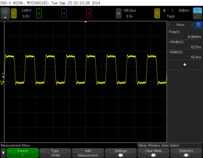
potatotron thanks for the code, lowest interval that I could get to work was microseconds=1, output was 290kHz@24mhz system clock or 500kHz @ 48mhz/96mhz system clock. I specified like so myTimer.begin(Clocker, 1). Based on the documentation it looks like I should be able specify a fractional interval(.125), but I cannot get any output. Tested on pin 13.
Demolishun, interesting, but I would prefer a simpler approach, something along the lines of what stevech suggested, if possible. Thanks for the link though, I will investigate it further when I get a chance.
-ren
PaulStoffregen
Well-known member
PaulStoffregen
Well-known member
Yes, since the peripheral clock is 48 MHz when the CPU runs at 48 or 96 MHz, but you can't get a 50% duty cycle.
Paul,
Any chance you could give me an example at 16mhz, I am having trouble determining the correct parameters.
Also, I was curious if you might be familiar with the code below. This is from Freescale app AN4627(zip file AN4627SW). This is to create a 24mhz clock. The faster the clock output I can generate, the better. So, of course, my next question would be, how could I get an output clock of 24mhz? I tried using the code in a sketch, in the setup function, but the width between the pulses vary. I suspect that this might be due to T3.1 onload init functions.
//#define FTM_24MHZ_PERIOD (0x00000001UL)
//#define FTM_24MHZ_DUTY (0x00000001UL)
void Set_FTM0(void)
{
SIM_SCGC6 |= SIM_SCGC6_FTM0_MASK; // Enable clock for FTM0
PORTC_PCR1 = PORT_PCR_MUX(0x04)|PORT_PCR_DSE_MASK; // Define pin for FTM0
FTM0_MOD = FTM_24MHZ_PERIOD; // PWM period
// Configure timers for edge aligned PWM High True Pulses
FTM0_C0SC = 0x28; // No Interrupts; High True pulses on Edge Aligned PWM
FTM0_C0V = FTM_24MHZ_DUTY; // 50% pulse width
FTM0_SC = 0x08; // Edge Aligned PWM running from BUSCLK / 1
}
Thanks,
-ren
- Status
- Not open for further replies.


