Markk
Well-known member
Hi
thank you all for the great work!
I'm trying to figure out the right way to use GND and AGND in a project. There is some info in another post, but I'm still unsure.
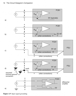
I'm not formally schooled and new in electronics, so I read a book about PCB design. I learned about ground loops, when and why they happen and what you can (and cannot) do about them.
My project involves a ground loop. It's the classic example of the supply going out to a sensor (possibly a bit away) and the signal coming back. In my case it's a high voltage supply (400V to 1500V photo multiplier tube). The voltage across the tube must be quite stable, as the tube's gain varies with the voltage to the power of 6 .. 9. So it's not so easy to shift things around there. The signal is a current pulse from (or rather into) the anode. It is decoupled through a cap to be conditioned and then digitized by the teensy. Obviously any sudden ground shifting adds error currents.
First I thought, brilliant, the Teensy has a separate AGND that I can connect the returning ground to and everything is nicely referenced to anythink picked up along the way. I wondered if I needed some dampening to keep the two (GND and AGND) reasonably close but I thought this was the way to go. Especially since the K20 datasheet (p. 11) suggests you can safely have +/-0.1V difference on VSS-VSSA.
But then I saw the ferrite in the Teensy 3.x schematic, tying AGND to GND. Ferrites are exotic beasts to me
A: Should I still go ahead and create the GND to AGND ground loop?
(And is the ferrite actually the kind of dampening one needs?)
B: Or should I remove the ferrite?
(And where is it? Any suggestions if I need to and how to damp instead?)
C: Or should I extend both GND and AGND pincers-like to the sensor, decoupling the high voltage to AGND out there (if this is the right terminology) and run all the signal conditioning curcuitry against AGND?
(And can AGND safely sink the max ~60 milliamps needed on startup?)
D: Or do I have to go the hard way, creating and working with a differential signal all the way back?
(the tricky part of the whole project is actually the signal conditioning, so I fear this would complicate things massively!)
E: Other options anyone?
This is still on the drawing board. I habe no practical experience. So I can't actually be sure if it's a real problem or if I'm overly cautious. I would just like to understand a bit more before I order PCBs.
Thanks for all your help.
-Markk


