Forum Rule: Always post complete source code & details to reproduce any issue!
Page 1 of 2 1 2 LastLast
Results 1 to 25 of 48

Thread: connecting nRF8001 to Teensy 3.1

  1. #1
    Junior Member
    Join Date
    Oct 2014
    Posts
    7

    connecting nRF8001 to Teensy 3.1

    Hi,

    I'm trying to hook up a nRF8001 from Adafruit to my Teensy 3.1 and run the Adafruit Guggenhat code on it. I downloaded the NRF8001 code from Paul Stoffregen's Github and everything compiles fine.

    When I hook it up to a Arduino Leonardo it all works fine and I can connect with nRF UART to the setup.
    When I do the same with Teensy 3.1 I cannot get it to work.

    I have the following shematics:

    nRF8001 <-> Teensy 3.1

    SCK <-> SCK (pin 13)
    MISO <-> DIN (pin 12)
    MOSI <-> DOUT (pin 11)
    REQ <-> PIN 10
    RDY <-> PIN 2
    RST <-> PIN 9
    GND <-> GND
    VIN <-> 3.3V

    I never get the nRF UART to connect to the setup. What is going wrong ?
    Can somebody help me ?
    As said, the code runs well on the Leonardo - nRF8001 setup
    not on Teensy 3.1, I run Teensyduino 1.20

    Thanks for helping out
    Rudy

  2. #2
    Senior Member onehorse's Avatar
    Join Date
    Apr 2014
    Location
    Danville, California
    Posts
    921
    I had problems using Adafruit's code on the Pro Mini 3V3 8 MHz AVR. The tutorial says you can use any pin for IIRC RDY or RST (off the top of my head I can't remember) and I chose a different pin than the one used in the tutorial. Well the sketch didn't work until I switched to exactly the pin used in the tutorial. Anyway, I am looking at my Pro Mini setup for the nRF8001 and it matches the schema you list above, so no help there...

  3. #3
    Junior Member
    Join Date
    Sep 2014
    Posts
    13

    Also having nRF8001 issues

    Rudy,

    Did you ever get the nRF8001 talking with your Teensy 3.1? I am having problems getting the echoDemo from Adafruit working. I am using a slightly different pinout than the example. Pin 9 for RDY is capable of interrupt on the Teensy, but I'm not sure if I need to do anything special to enable it.

    I am watching all the SPI pins on a logic analyzer, and I can see a valid "device started" event after a reset (x01, x04, x81, x02, x00, x02). Nothing else ever happens over the SPI bus after that first traffic, though. Let me know if this is similar to your issue. If not, I'll post in another thread.

    I should also mention for completeness that I pulled the regulator off the Bluefruit LE board my nRF8001 is on, and I am supplying 3.3V from the Teensy. I am pretty sure this is working fine since I can see the initial traffic. It is the Teensy's turn to talk, and it has 2 data credits available per the nRF8001, but nothing else happens over the SPI to continue the setup procedure.

    Thanks,
    - Jarrod

    Code:
    /*********************************************************************
    This is an example for our nRF8001 Bluetooth Low Energy Breakout
    
      Pick one up today in the adafruit shop!
      ------> http://www.adafruit.com/products/1697
    
    Adafruit invests time and resources providing this open source code, 
    please support Adafruit and open-source hardware by purchasing 
    products from Adafruit!
    
    Written by Kevin Townsend/KTOWN  for Adafruit Industries.  
    MIT license, check LICENSE for more information
    All text above, and the splash screen below must be included in any redistribution
    *********************************************************************/
    
    // This version uses the internal data queing so you can treat it like Serial (kinda)!
    
    #include <SPI.h>
    #include "Adafruit_BLE_UART.h"
    
    // Connect CLK/MISO/MOSI to hardware SPI
    // e.g. On UNO & compatible: CLK = 13, MISO = 12, MOSI = 11
    #define ADAFRUITBLE_REQ 10
    //#define ADAFRUITBLE_RDY 2     // This should be an interrupt pin, on Uno thats #2 or #3
    #define ADAFRUITBLE_RDY 9     // This should be an interrupt pin, on Uno thats #2 or #3
    //#define ADAFRUITBLE_RST 9
    #define ADAFRUITBLE_RST 17
    #define MEMCS_N 22
    
    Adafruit_BLE_UART BTLEserial = Adafruit_BLE_UART(ADAFRUITBLE_REQ, ADAFRUITBLE_RDY, ADAFRUITBLE_RST);
    /**************************************************************************/
    /*!
        Configure the Arduino and start advertising with the radio
    */
    /**************************************************************************/
    void setup(void)
    { 
      pinMode(MEMCS_N, OUTPUT);
      Serial.begin(9600);
      delayMicroseconds(300000); // Delay added so serial message shows up on monitor after reset
      Serial.println(F("Adafruit Bluefruit Low Energy nRF8001 Print echo demo"));
      BTLEserial.begin();
      
    }
    
    /**************************************************************************/
    /*!
        Constantly checks for new events on the nRF8001
    */
    /**************************************************************************/
    aci_evt_opcode_t laststatus = ACI_EVT_DISCONNECTED;
    
    int printmessages = 0;
    void loop()
    {
      digitalWrite(MEMCS_N, HIGH);   // hold the memory CS_N high to avoid bus contention
      // Tell the nRF8001 to do whatever it should be working on.
      BTLEserial.pollACI();
      if (printmessages < 10) {
         Serial.print(printmessages,DEC);
         Serial.print(" Last status = 0x");
         Serial.print(laststatus, HEX);
         Serial.print(F("\n"));
         printmessages++;
    
      }
     
    
      // Ask what is our current status
      aci_evt_opcode_t status = BTLEserial.getState();
      // If the status changed....
      if (printmessages < 10) {
         Serial.print(F("Status = 0x"));
         Serial.print(status, HEX);
         Serial.print(F("\n"));
         //delayMicroseconds(1000000);
      }
      
      if (status != laststatus) {
        // print it out!
        if (status == ACI_EVT_DEVICE_STARTED) {
            Serial.println(F("* Advertising started"));
        }
        if (status == ACI_EVT_CONNECTED) {
            Serial.println(F("* Connected!"));
        }
        if (status == ACI_EVT_DISCONNECTED) {
            Serial.println(F("* Disconnected or advertising timed out"));
        }
        // OK set the last status change to this one
        laststatus = status;
      }
      
      if (status == ACI_EVT_CONNECTED) {
        // Lets see if there's any data for us!
        if (BTLEserial.available()) {
          Serial.print("* "); Serial.print(BTLEserial.available()); Serial.println(F(" bytes available from BTLE"));
        }
        // OK while we still have something to read, get a character and print it out
        while (BTLEserial.available()) {
          char c = BTLEserial.read();
          Serial.print(c);
        }
        
        // Next up, see if we have any data to get from the Serial console
    
        if (Serial.available()) {
          // Read a line from Serial
          Serial.setTimeout(100); // 100 millisecond timeout
          String s = Serial.readString();
    
          // We need to convert the line to bytes, no more than 20 at this time
          uint8_t sendbuffer[20];
          s.getBytes(sendbuffer, 20);
          char sendbuffersize = min(20, s.length());
          
          Serial.print(F("\n* Sending -> \"")); Serial.print((char *)sendbuffer); Serial.println("\"");
          
          // write the data
          BTLEserial.write(sendbuffer, sendbuffersize);
        }
      }
    }

  4. #4
    Junior Member
    Join Date
    Oct 2014
    Posts
    7
    Hi Jarrod,

    I never got it to work, i'm going to try One more thing tomorrow by putting 5v on the nRF8001. I'll post my results.

    KR,Rudy

  5. #5
    Junior Member
    Join Date
    Sep 2014
    Posts
    13
    Hi Rudy,

    The Bluefruit LE has a regulator between VIN (pin 10) and VDD (3Vo pin 8), so it is expecting you to apply 5V to pin 10 and float pin 8 or pull 3.3V power out of pin 8. The Bluefruit LE nRF8001 breakout board is not set up to drive 3.3V power into pin 8 - or pin 10 for that matter. It is expecting 5V into pin 10.

    On the software side, I didn't have luck with the Adafruit echoDemo, but I found a post from tato123 on the Adafruit forum working directly with the Nordic Semiconductor code instead of the Adafruit code. I downloaded his code, modified my pin assignments and got the ble_A_Hello_World_Program to connect first try. Here's the link.


    https://github.com/tato123/nrf8001_arm_support


    The Nordic example code is different than the Adafruit code, so it might not help you get the Guggenhat running.

    Best of luck,
    - Jarrod

  6. #6
    Junior Member
    Join Date
    Oct 2014
    Posts
    7

    connecting nRF8001 to Teensy 3.1

    Hi Jarrod,

    I tried by supplying 5V to the nRF8001 breakout board, it didn't help.
    Running the code from Tato123 seems not that easy, it looks not to be Arduino code.
    I'm afraid I'll have to give up on running this on Teensy, that is really a pitty.
    Thanks for your suggestions.

    KR,
    Rudy

  7. #7
    Hi Rudy,

    tato123 also published an Arduino compatible library: https://github.com/tato123/Adafruit_nRF8001
    I used this library for a project with a Teensy 3.1 and a nRF8001 board (the one from Olimex).

    Best,
    Ferdinand

  8. #8
    Junior Member
    Join Date
    Oct 2014
    Posts
    7

    connecting nRF8001 to Teensy 3.1

    Hi Ferdinand,

    Thanks for the help, I used the library you referred to and still no luck for me, I simply don't get it to work on Teensy 3.1. It compiles and does nothing.
    When compiling exactly the same code for Leonardo the Bluetooth connection comes on immediately.

    I don't get what I'm doing wrong here ...

    Thanks anyhow

    KR,
    Rudy

  9. #9
    Hi, I am experiencing the same thing, I have the same pin connections as the first post and also tried with pin 3 instead of 2 for RDY

    I tried the library from adafruit , tato and pauls version on github.

    All worked with an arduino uno but nothing on the teensy.

    The teensy vusb has been cut, and is externally powered by a 5V wall supply. The teensy itself works fine with other projects.

    When using the uno I tried connecting the nrf8001 via both the 5v and 3V pins on the uno, both worked.

    On the teensy I am using the 3.3v pin (next to pin 23)

    On the android device used to connect to the adapter using the nordic generic app, it fails to find the device,
    occasionally a "null" device is detected however connecting to this succeeds but is unable to communicate with the demo sketches provided with the lib.

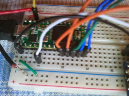
    I have attached a photo of the teensy side wiring.

    Has anyone else run into this and found a solution ?

    thanks
    Lynton
    Attached Thumbnails Attached Thumbnails Click image for larger version. 

Name:	teensy_nrf8001.jpg 
Views:	267 
Size:	90.6 KB 
ID:	2842  

  10. #10
    I just looked at the adafruit guggenhat example mentioned by Rudyv in the first post and found this :

    "Cutting-edge boards like the Arduino Due, Netduino or Teensy 3 are unlikely to work here — though powerful, they’re based on different processors and only “mostly” Arduino compatible."

    This does not really explain why, but it does looks like I am out of luck trying to get this to work on a teensy

    From Paul's comments in the library it has been updated to work on non AVR processors, so I'm hoping he can shed some light on this.

  11. #11
    Senior Member PaulStoffregen's Avatar
    Join Date
    Nov 2012
    Posts
    28,468
    Here is my attempt to fix the library for 32 bit ARM (Teensy 3.1)

    https://github.com/PaulStoffregen/Adafruit_nRF8001

    I have verified this code on an Arduino Uno and a Teensy 3.1, with the Adafruit nRF8001 breakout, and an iPad Mini running the "Bluefruit LE" UART app.

    If anyone is still watching this thread, please give it a try and let me know how it works for you?

  12. #12

    works for me now.

    Quote Originally Posted by PaulStoffregen View Post
    Here is my attempt to fix the library for 32 bit ARM (Teensy 3.1)

    https://github.com/PaulStoffregen/Adafruit_nRF8001

    I have verified this code on an Arduino Uno and a Teensy 3.1, with the Adafruit nRF8001 breakout, and an iPad Mini running the "Bluefruit LE" UART app.

    If anyone is still watching this thread, please give it a try and let me know how it works for you?
    Just tried this and it worked for me using android nrf UART 2.0 app with both the callbackecho and echodemo sketches.

    Thanks paul.

  13. #13
    Senior Member PaulStoffregen's Avatar
    Join Date
    Nov 2012
    Posts
    28,468
    Thanks for the followup. I'm going to send it to Adafruit now...

  14. #14
    Senior Member
    Join Date
    Jan 2013
    Location
    San Francisco Bay Area
    Posts
    660
    Nice!

    I'll have to order one to try it out.

  15. #15
    For the OP (rudyv) , I can confirm that the adafruit guggenhat example code also works now with teensy 3.1 and the adafruit bluetooth LE breakout.

  16. #16
    Junior Member
    Join Date
    Oct 2014
    Posts
    7
    Quote Originally Posted by lynton View Post
    For the OP (rudyv) , I can confirm that the adafruit guggenhat example code also works now with teensy 3.1 and the adafruit bluetooth LE breakout.
    Thanks for the feedback, @Paul and @ Lynton, unfortunately I didn't get it to work, I got the latest version from Paul from the Web, I did see he still changed something in the Utilities, maybe that is the reason.

    @Paul, can you check ?

    Thanks,
    KR,
    Rudy

  17. #17
    Quote Originally Posted by Rudyv View Post
    Thanks for the feedback, @Paul and @ Lynton, unfortunately I didn't get it to work
    I had to modify the guggenhat code #define LED 13 -> 3 to get it to work as 13 is being used for the BLE sck pin, but guggenhat uses it to blink the onboard LED, setting this to unused pin 3 made it work for me without the blinking of course.

  18. #18
    Junior Member
    Join Date
    Oct 2014
    Posts
    7
    Quote Originally Posted by lynton View Post
    I had to modify the guggenhat code #define LED 13 -> 3 to get it to work as 13 is being used for the BLE sck pin, but guggenhat uses it to blink the onboard LED, setting this to unused pin 3 made it work for me without the blinking of course.
    Hi Lynton,

    I got it to work, I grabbed the library posted by Paul at the adafruit Github and changed the LED 13 -> 3 and now it finally works.

    Thanks,
    Rudy

  19. #19
    Hi Rudyv,

    Glad to hear it works for you too now.

    I also want to read a micro SD card in my application but this currently causes conflicts with the SdFat library.

    Paul is currently working on implementing SPI transactions in the library so that it can work in conjunction with other interrupt based SPI libraries. So you may want to look at this thread too if you plan to include SdFat or any other interrupt based SPI libs with nRF8001

    http://forum.pjrc.com/threads/27069-...1?goto=newpost

  20. #20
    Quote Originally Posted by lynton View Post
    Just tried this and it worked for me using android nrf UART 2.0 app with both the callbackecho and echodemo sketches.

    Thanks paul.
    I'm not able to get this to connect, or even show up, in either the Bluefruit LE or nRFUART app version 1.0.1 on iPhone. I see the initial text in the serial window on my PC, but the bluetooth doesn't show up in the applications. I wired it up according to Paul's pinouts. VIn on the Bluetooth is connected to the USB power and the trace is not cut.

    Is there a debugging step I should take at this point?

  21. #21
    Quote Originally Posted by BloomingtonFPV View Post
    Is there a debugging step I should take at this point?
    I assume you have already changed pin 13 as mentioned earlier, if not try that,)

    have you tried it with an arduino ?, this would prove that the BLE is or is not ok.
    you may have to reduce the number of pixels for the arduino to have enough memory to run the giggen hat example.

    You could try it with an external power supply, and cut vusb, it's better that way anyway and then no risk to your laptop.

  22. #22
    Quote Originally Posted by lynton View Post
    I assume you have already changed pin 13 as mentioned earlier, if not try that,)

    have you tried it with an arduino ?, this would prove that the BLE is or is not ok.
    you may have to reduce the number of pixels for the arduino to have enough memory to run the giggen hat example.

    You could try it with an external power supply, and cut vusb, it's better that way anyway and then no risk to your laptop.
    I'm just using the CallbackEcho demo.
    I'm using these pinouts for the Teensy 3.1:
    SCK -> Pin 13
    MISO -> Pin 12
    MOSI -> Pin 11
    REQ -> Pin 10
    RDY -> Pin 2 (HW interrupt)
    ACT -> Not connected
    RST -> Pin 9
    3V0 - > Not connected
    GND -> GND
    VIN -> 5V

    but it occurs to me that these might only be for the UNO. Could someone list the pinouts for the Teensy 3.1?

  23. #23
    Senior Member PaulStoffregen's Avatar
    Join Date
    Nov 2012
    Posts
    28,468
    Those same connections work for Teensy 3.1.

  24. #24
    Senior Member PaulStoffregen's Avatar
    Join Date
    Nov 2012
    Posts
    28,468
    Quote Originally Posted by BloomingtonFPV View Post
    Is there a debugging step I should take at this point?
    Those connections should work. Maybe post a photo of your wiring. If something isn't connected right, maybe we'll be able to see it?

    Also, what are you seeing in the Arduino Serial Monitor?

  25. #25
    It is weird. I can get the first serial line the first time it runs, but if I close and re-open the serial window the program doesn't run. It's like the program hangs.

    Here are the pictures:

    https://www.flickr.com/photos/125602...7648998610657/

    Note that I have an I2C device and a serial device wired in as well. Both of these are working even though the bluetooth is installed.

    Sorry about the small depth of field. Hopefully you can see the wiring connects.

    Here is how I set up the software. I downloaded the .zip file from the github site. I started arduino 1.0.6 and went to import libraries. I selected the .zip file. I then closed arduino and reopened it. I selected callbackdemo and it compiled and uploaded. The first time it runs I get the serial output line, but I have to re-upload to see it again.

Posting Permissions

  • You may not post new threads
  • You may not post replies
  • You may not post attachments
  • You may not edit your posts
  •