Hello together,
today I soldered the new prototype boards for my project, a cheap-thermographic camera.
It's my first custom Teensy design, so I orientated myself on the schematic available on this site.
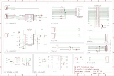
It contains a Lipo Charging / Boosting / Measuring circuit, a display connector and some peripherals.
But for testing purposes, I skipped the battery part and connected 5V USB power directly to VREGIN on the MCU so that part doesnt matter.
I assembled two boards, but the Teensy is not recognized at all. No sign of life at all, so I don't know where to start fixing.
If someone can PLEASE check my design, that would be very helpful in order to eliminate wiring mistakes.
Then its just my bad soldering skills and I can order new boards
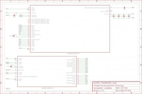
Here is the schematic:


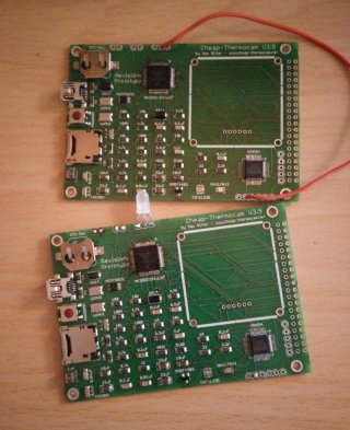
Its looking like this: (red wire is connecting 5V USB to VREGIN):

Thanks in advantage for any help
Max
today I soldered the new prototype boards for my project, a cheap-thermographic camera.
It's my first custom Teensy design, so I orientated myself on the schematic available on this site.
It contains a Lipo Charging / Boosting / Measuring circuit, a display connector and some peripherals.
But for testing purposes, I skipped the battery part and connected 5V USB power directly to VREGIN on the MCU so that part doesnt matter.
I assembled two boards, but the Teensy is not recognized at all. No sign of life at all, so I don't know where to start fixing.
If someone can PLEASE check my design, that would be very helpful in order to eliminate wiring mistakes.
Then its just my bad soldering skills and I can order new boards
Here is the schematic:


Its looking like this: (red wire is connecting 5V USB to VREGIN):

Thanks in advantage for any help
Max
Last edited:

