
You are using an out of date browser. It may not display this or other websites correctly.
You should upgrade or use an alternative browser.
You should upgrade or use an alternative browser.
Interfacing with TI DAC856x, DAC816x, or DAC756x
- Thread starter jcarruthers
- Start date
- Status
- Not open for further replies.
jcarruthers
Well-known member
Thanks Nantonos — very useful link. Thusly — 220R innie, plus the capacitor from input to output:

jcarruthers
Well-known member
I put together this schematic on some stripboard — though not with the variable resistor.
The thing is totally spot on from C0 to C4 (0v to -4v) — going upwards from 0v it's not _quite_ as accurate but only ever off by a hertz or so up C6 — drifts very slightly from then onwards obviously as you get higher in pitch a couple of hertz doesn't really make a huge difference (I can't hear it anyway)
I think an 8 octave range is pretty decent.
jcarruthers
Well-known member
Some results —*using my multimeter for both freq and voltage — I would question the accuracy of multimeter and possibly the VCO.
Code:
Hz      volts

  16.4 = -4.99x
  33.3 = -3.995
  66.4 = -3.000
 130.8 = -2.001
 260.9 = -1.001
 520.0 = -0.001
1038   = 0.998
2069   = 1.998
4120   = 2.997
819x = 3.997Well done. Yes, its not the number of Hertz (the difference) but the ratio of the frequencies that matters. So as you go up the scale, the pitches correspond to larger and larger frequencies and their differences will be larger even with a constant error.The thing is totally spot on from C0 to C4 (0v to -4v) — going upwards from 0v it's not _quite_ as accurate but only ever off by a hertz or so up C6 — drifts very slightly from then onwards obviously as you get higher in pitch a couple of hertz doesn't really make a huge difference (I can't hear it anyway)
The way to compare them is to calculate the ratio of observed to expected frequency and express this in cents, where 100 cents is a semitione and 120 cents is an octave. The formula is
cents = 1200 * log2 (Fobs/Fexp)
or (using base 10 logs like you find on a calculator)
cents = 1200 * (log(Fobs/Fexp) / log(2))
or using this online calculator.
Yes, it is an excellent result. To put that into context, many commercial systems only claim tracking over five octaves and some achieve even less. Comparison between systems is made harder because they typically don't give any numerical bounds for what margin of error they count as "tracking well". But you did, in your next post, so well done again.I think an 8 octave range is pretty decent.
jcarruthers
Well-known member
Thanks Nantonos —*but really I did nothing —*it's all thanks to you and mxxx.
Looking at the measured results again (after your extended explanation) it is pretty good — but then I guess it's using fairly expensive ICs. The only odd result is the -2.001 reading —*but I think my multimeter has better accuracy than the VCO I'm using (fairly expensive Tiptop Z3000) —*my main thing is ensuring that the output of _my_ circuit is right.
I should point out that I didn't have the right value capacitor for both the opamp circuit and the recommended one for the DACs VREF output — so it should be even better once I put those in.
I also realised this morning I put a 1k resistor between the feedback loop and the output — I am not sure what effect this has except for taking the mA down.
Looking at your results, the voltage measurements say how well the DAC and buffer combination is doing. This should normally be measured into a fixed load, say 100k, but in your case the output buffer has a very low output impedance making the voltage almost independent of load.
Given the constraints of your meter, all you can say is that the circuit is performing correctly. Any errors in the trimming of the circuit are swamped by errors in the meter and can't be measured directly. (They can, within some constraints, be measured indirectly).
The frequency measurements say how well the complete system of DAC, buffer, and oscillator is doing. Again the sources of error in the measurement are the system itself and the meter used to measure it.
The tracking of an analog oscillator is determined by the linearity of the exponential converter and the care taken to correct capacitance losses at higher frequencies. (This is why some oscillators have range or footing switches; they switch in different values of capacitance so that on a given range they have to cover less octaves and are thus less affected by high frequency error). A digital oscillator should track a large number of octaves as it is immune to those effects.
For the measurement, there are two ways to measure frequency (count cycles in a fixed period of time, or time one cycle) which have different error behaviour; the first is accurate at high frequencies but inaccurate at very low ones and the second is the opposite way around. I suspect that your meter is using the first method, as it is both more accurate and quicker for most frequencies of interest; that may explain the non-linearity in the errors towards the lower octaves.
So, lets look at your frequency results expressed as errors in cents. 100 cents is a semitone. 50cents is an easily heard error. 20 to 10 cents is hard to hear (depends a lot on the person and their sense of pitch). Below 10 cents is imperceptible even for people with perfect pitch.
In general excellent, there is a bit of non-linearity on the lower octaves. That might be due to measurement inaccuracy and there are also less digits of precision in the lowest measurements.
As there are ten measurements, we can look at the overal linearity and guess (with more confidence than we could from a single measurement) that the gain of the op-amp buffer is very slightly less than it should be.
Looking at a linear regression of the the frequencies (in cents relative to the 0V frequency) from the best seven octaves only (to avoid what seems to be low frequency measurement error, and dropping the uppermost octave as well) I get a slope of 1192.5 when it should be 1200. So a slight trim to increase the gain might give even better tracking. This error probably is due to the tolerance of the resistors used to set the gain.
Given the constraints of your meter, all you can say is that the circuit is performing correctly. Any errors in the trimming of the circuit are swamped by errors in the meter and can't be measured directly. (They can, within some constraints, be measured indirectly).
The frequency measurements say how well the complete system of DAC, buffer, and oscillator is doing. Again the sources of error in the measurement are the system itself and the meter used to measure it.
The tracking of an analog oscillator is determined by the linearity of the exponential converter and the care taken to correct capacitance losses at higher frequencies. (This is why some oscillators have range or footing switches; they switch in different values of capacitance so that on a given range they have to cover less octaves and are thus less affected by high frequency error). A digital oscillator should track a large number of octaves as it is immune to those effects.
For the measurement, there are two ways to measure frequency (count cycles in a fixed period of time, or time one cycle) which have different error behaviour; the first is accurate at high frequencies but inaccurate at very low ones and the second is the opposite way around. I suspect that your meter is using the first method, as it is both more accurate and quicker for most frequencies of interest; that may explain the non-linearity in the errors towards the lower octaves.
So, lets look at your frequency results expressed as errors in cents. 100 cents is a semitone. 50cents is an easily heard error. 20 to 10 cents is hard to hear (depends a lot on the person and their sense of pitch). Below 10 cents is imperceptible even for people with perfect pitch.
Code:
Freq	   Ratio	   Cents	Error
16.4	   0.031538	   -5984.0	15.907
33.4	   0.064230	   -4752.7	47.290
66.4	   0.127692	   -3563.1	36.892
130.8	   0.251538	   -2389.3	10.621
260.9	   0.501730	   -1194.0	5.9823
520.0	   1.000000	   1.0000	0
1038	   1.99615	   1196.6	-3.3325
2069	   3.97884	   2390.8	-9.1798
4120	   7.92307	   3583.2	-16.727
8194.5 15.7586 4773.6 -26.313As there are ten measurements, we can look at the overal linearity and guess (with more confidence than we could from a single measurement) that the gain of the op-amp buffer is very slightly less than it should be.
Looking at a linear regression of the the frequencies (in cents relative to the 0V frequency) from the best seven octaves only (to avoid what seems to be low frequency measurement error, and dropping the uppermost octave as well) I get a slope of 1192.5 when it should be 1200. So a slight trim to increase the gain might give even better tracking. This error probably is due to the tolerance of the resistors used to set the gain.
Last edited:
jcarruthers
Well-known member
FYI my method of "digital" calibration was to set the output to 0 volts and then apply a correction — I only needed to add 66/65536 or 0.001% to get it spot on to zero (at least spot on with my multimeter)
I'm sure I could easily add a calibration value for each volt and get it even more spot on.
I'm sure I could easily add a calibration value for each volt and get it even more spot on.
jcarruthers
Well-known member
Have been playing around with the DAC a bit more – works really well for CV control — envelopes, LFO etc
Testing out the ability to make tone (firstly it was to do LFO stuff, but it works with higher frequencies too) using this:
Testing with my multimeter it's spot on — though low frequencies are rather quiet when playing through the modular.
Testing out the ability to make tone (firstly it was to do LFO stuff, but it works with higher frequencies too) using this:
Code:
unsigned long sinWave(float hz) {
  float usfrac = micros() / 1000000.0;
  float angle = (twopi * hz) * usfrac;
  return (32768 * sin(angle)) + 32768;
}
Testing with my multimeter it's spot on — though low frequencies are rather quiet when playing through the modular.
Last edited:
Remember that you have the whole of the audio library, which can be used with the onboard DAC as the output. So if you want, say 16 detuned saw waves going through a bandpass filter modulated by an LFO, you can do all that on the one Teensy 3.1 and output the result through the DAC.
jcarruthers
Well-known member
I presume if I was feeling really brave I could mod the audio library to work with the TI DAC?
Maybe. Sending audio-rate data over SPI is stretching things a bit and would use up a lot of your CPU.
However, the TI DAC is primarily for DC accuracy so great for accurate CV. The DAC on the audio board or on Mxmxmx's module is primarily for audo (and uses a protocol, I2S, designed for streaming audio) so more attention is paid to harmonic distortion and so on, less to DC accuracy. The onboard DAC isn't really optimised for either, but it is sitting there unused and can give good results with a bit of filtering and some care (plus the audio library supports it already and uses efficient block moves of data over DMA to feed the DAC).
However, the TI DAC is primarily for DC accuracy so great for accurate CV. The DAC on the audio board or on Mxmxmx's module is primarily for audo (and uses a protocol, I2S, designed for streaming audio) so more attention is paid to harmonic distortion and so on, less to DC accuracy. The onboard DAC isn't really optimised for either, but it is sitting there unused and can give good results with a bit of filtering and some care (plus the audio library supports it already and uses efficient block moves of data over DMA to feed the DAC).
I failed to notice this:
If the module has 100k input, you end up with 0.99 V/octave. If it has a 100k pot as the input, you end up with 0.98 to 0.99V/octave depending on the pot position. If you send the output to two modules in parallel each with 50k input you get 0.96 V/octave. That error is cumulative, so over 5 octaves you have 5 times the tuning error and so on.
That is the whole reason for the two resistors and one cap feedback circuit - the output has very low output imedance and is effectively insensitive to load.
Cut through the 1k resistor and solder a wire link to reconnect the two ends.
What that does is make the output impedance 1k. This combines with the input impedance of the module(s) you are driving to form a resistive divider.I also realised this morning I put a 1k resistor between the feedback loop and the output — I am not sure what effect this has except for taking the mA down.
If the module has 100k input, you end up with 0.99 V/octave. If it has a 100k pot as the input, you end up with 0.98 to 0.99V/octave depending on the pot position. If you send the output to two modules in parallel each with 50k input you get 0.96 V/octave. That error is cumulative, so over 5 octaves you have 5 times the tuning error and so on.
That is the whole reason for the two resistors and one cap feedback circuit - the output has very low output imedance and is effectively insensitive to load.
Cut through the 1k resistor and solder a wire link to reconnect the two ends.
The posted measurements for this DAC promted me to actually getting around to measuring the output voltage produced by my own pitch DAC board. It uses an AD5532 16-bit DAC, an AD780 voltage reference and two OPA2277PA op-amps plus a couple of trimmers (one for offset, one for gain). I also measured the resulting frequencies produced by a Dixie 2 VCO driven by that DAC. The results are over on Muffs forum for the curious. In summary, the voltages were spot-on over a 10V range withing the limits of my 40,000 count voltmeter and the pitches were accurate with a maximum error of 8 cents over those 10 octaves, subject to the limits of the frequency meter I was using at frequencies below 400Hz.
The schematic and PCB are on my github, also some documentation. The PCB has an error, I meant to connect DGND and AGND with an inductor, then decided not to, but failed to add a trace to connect them. So a short wire needs to be added to connect the two grounds.
The schematic and PCB are on my github, also some documentation. The PCB has an error, I meant to connect DGND and AGND with an inductor, then decided not to, but failed to add a trace to connect them. So a short wire needs to be added to connect the two grounds.
jcarruthers
Well-known member
Thanks again Nantonos
Your results are pretty awesome.
Also nice to know the Intellijel stuff is great - I am loving my Atlantis.
I see you also have an opamp to buffer? I presume that isnt needed in mine as it appears to work well already.
I treated myself to a scope yesterday (Rigol DS1074) - it should be arriving today. I'm looking forward to seeing properly.
I'm guessing it might also have a decent accurcy for measuring the voltage.
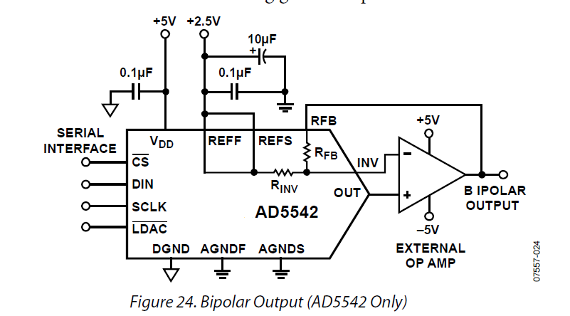
That particular DAC has pins to allow it to connect to a bipolar-powered op-amp and give bipolar output even though the DAC has a unipolar power supply. That gets me to ±2.5V and the other three take me to -2.5V to +7.5V. The op-amp circuit you drew in post #27 is a buffer.
I was chuffed to see Dr. Sketch-n-Etch (David Dixon, designer of the Dixie and a bunch of other Intellijel modules) commenting on my post")
A scope certainly helps see what is happening, but its not as accurate for single voltage measurements as a good multimeter. Check the spec sheet to see what the accuracy is.
I was chuffed to see Dr. Sketch-n-Etch (David Dixon, designer of the Dixie and a bunch of other Intellijel modules) commenting on my post
A scope certainly helps see what is happening, but its not as accurate for single voltage measurements as a good multimeter. Check the spec sheet to see what the accuracy is.
jcarruthers
Well-known member
I'm mainly wanting to see what is happening with both pitch and cv outputs - it gets tiresome to listen all the time and wonder. (Pitch changing against cv/gate - I'm doing some funky things in code that I want to check)
This is what it says in the spec:
DC Gain Accuracy[3]
<10 mV: ±4% full scale
≥10 mV: ±3% full scale
DC offset
±0.1 div ± 2 mV ± 1% offset
This is what it says in the spec:
DC Gain Accuracy[3]
<10 mV: ±4% full scale
≥10 mV: ±3% full scale
DC offset
±0.1 div ± 2 mV ± 1% offset
That particular DAC has pins to allow it to connect to a bipolar-powered op-amp and give bipolar output even though the DAC has a unipolar power supply. That gets me to ±2.5V and the other three take me to -2.5V to +7.5V. The op-amp circuit you drew in post #27 is a buffer.
out of curiosity - may i ask is there a specific reason why you didn't use just one op amp (ie inverting 2x gain + trimpot/offset)?
jcarruthers
Well-known member
Playing with my new oscilloscope this evening:
A digital C5 sine wave

Comparing the DAC to a Tiptop Z3000 and Atlantis (all "sine" waves)

I am wondering; the DAC has an SPI freq of 50Mhz — how do I know I'm using all of it? And what is the full audio freq I can get out of it?
A digital C5 sine wave
Comparing the DAC to a Tiptop Z3000 and Atlantis (all "sine" waves)
I am wondering; the DAC has an SPI freq of 50Mhz — how do I know I'm using all of it? And what is the full audio freq I can get out of it?
I am wondering; the DAC has an SPI freq of 50Mhz — how do I know I'm using all of it? And what is the full audio freq I can get out of it?
the teensy's max SPI clock is 24Mhz, so you can't use all of it (ie 50 MHz). i'm not quite up to date with the SPI library so not sure what it defaults to, but at any rate you can set it with SPI.beginTransaction(SPISettings(speed, order, mode)) -- see https://www.pjrc.com/teensy/td_libs_SPI.html
that value will be just one (probably minor) factor as regards output at audio frequency. assuming you'll be doing some kind of DDS, output frequency + limits thereof is a function of the sample clock frequency of your DDS system, not the SPI clock (though that'll be a limiting factor). IIRC, the orgone accumulator for instance uses 80kHz. i don't know what's practical with SPI and you'd probably want to use dmaSPI which i think isn't quite there yet. a suitable output stage will look somewhat different as well. either way, as nantonos said, given there's the audio library/i2s, and audio DACs/codecs tending to be cheaper than those TI DACs, why not use one.
jcarruthers
Well-known member
I'll have to make a decision on audio DAC vs mine.
I need the precision for the pitch CV —*and I'm happy with the one I chose for that.
The reason for thinking about audio is that I'm doing some funky pitch bends. The other CV out is going to be used for envelope.
Regardless — I presume I can do "audio" just at a lower rate —*which is probably enough.
My not-based-on-anything calculations — each write is 24bits — @ 44100Hz it only needs a couple of Mhz if it was streaming out bits.
out of curiosity - may i ask is there a specific reason why you didn't use just one op amp (ie inverting 2x gain + trimpot/offset)?
I can see how I could have combined three of them (-2x gain and summing, and 2.5V ref into the positive input) but not how that could be combined with the bipolar output amp to get it down to one op-amp overall, because the resistors for the bipolar output are inside the DAC.
(I didn't do it that way because combining inverting and non-inverting summing on one amp seemed complicated. Although, not for one input on the non-inverting, I suppose). However, I'm pleased with the measured performance of the circuit.
the resistors for the bipolar output are inside the DAC.
ah, i see. i didn't look into the part/assumed it's run off bipolar supplies. that wouldn't work then.*
obviously it's performing well, i was just curious about the 4 op amps.
(* though, for the sake of $/parts count, i figure one still could reduce it to one op amp**, as you have the negative rail there. say, use a lm4040 to get - 5v. then: inverting mixer: (- 4 x 2.5 (DAC)) + (-1.5 * -5 (Vref)) = -2.5/7.5 swing. or keep the ad780 and invert that first: two op amps)
** in principle, i'm not saying it would work just as well.
Last edited:
The best (A Grade) LM4040A25 has an initial accuracy of Max 0.1% (2.5mV), a voltage drift with temperature of 100 ppm/°C. Noise is 35 μV RMS.
AD780BN has an initial accuracy of 1.0mV, a temperature dependance of 3 ppm/°C, line regulation of 10μV/V and load regulaton over a 0-10mA range of 50
μV/mA sourcing and 75μV/mA sinking. It also has low output noise of 4μV p-p and long term stability of ±20 ppm/1000 Hr.
High accuracy, and stability over temperature and time, was the main design goal for this circuit. The measured output voltage of the AD780BN was 2.5001V (1mV error, at the limit of my meter for that range).
The best (A Grade) LM4040A25 has an initial accuracy of Max 0.1% (2.5mV), a voltage drift with temperature of 100 ppm/°C. Noise is 35 μV RMS.
AD780BN has an initial accuracy of 1.0mV, a temperature dependance of 3 ppm/°C, line regulation of 10μV/V and load regulaton over a 0-10mA range of 50
μV/mA sourcing and 75μV/mA sinking. It also has low output noise of 4μV p-p and long term stability of ±20 ppm/1000 Hr.
High accuracy, and stability over temperature and time, was the main design goal for this circuit. The measured output voltage of the AD780BN was 2.5001V (1mV error, at the limit of my meter for that range).
why, sure. as i said, i was wondering whether there was a deeper reason behind the 4 op amps (rather than 1-2), not the choice of the reference.
Last edited:
- Status
- Not open for further replies.