DIY Teensy woes

Status
Not open for further replies.

mattomatto

Well-known member
Hi all,

I received my second round of PCBs based on the teensy and audio shield schematics put together and am disappointed to say that once again I cannot get them to work. I am burning through the Mini54 chips at the moment!

My last design appeared to work - the verbose output form the teensy loader said everything it was supposed to, but the MK20 just did nothing. I went back and greatly simplified the circuit and improved the decoupling. This time, I get nothing from either chip. While I'm not an EE, I think I understand the design principals well and am really pulling my hair out trying to sus out why they don't work.

One slightly important change I made was I am now using this crystal:
http://uk.farnell.com/jsp/search/productdetail.jsp?SKU=1841946

Would that be appropriate to use for the MK20? Should I be adding 18pF caps to it?

I have tested all connections and have made several boards to eliminate the possibility of bad soldering.

If anyone would be kind enough to look at my designs and offer some ideas, I would be very grateful.

Here are the schematic and layout:

https://drive.google.com/file/d/0BwUFiZpwTq6WTmplanZzRXVzNXc/view?usp=sharing

https://drive.google.com/file/d/0BwUFiZpwTq6WdGFrOTNsNEhrV1E/view?usp=sharing


Before you ask - I do already use the teensy and audio shield a LOT and this isn't just to try and make my own board for cheaper - It's my hobby and I just feel compelled to make it work because it would be awesome!

Many thanks,

Matt
 
Last edited:
One slightly important change I made was I am now using this crystal:
http://uk.farnell.com/jsp/search/productdetail.jsp?SKU=1841946

Would that be appropriate to use for the MK20? Should I be adding 18pF caps to it?

You can change the capacitance from software only, by writing a different value to OSC0_CR. Edit the code here:

https://github.com/PaulStoffregen/cores/blob/master/teensy3/mk20dx128.c#L441

Refer to the MK20 reference manual for documentation on OSC0_CR.


Before you ask - I do already use the teensy and audio shield a LOT and this isn't just to try and make my own board for cheaper - It's my hobby and I just feel compelled to make it work because it would be awesome!

Either is perfectly fine. But bringing up brand new hardware can be tricky, even when based on a known-good design. Details matter and electrons can be very unforgiving.

I can't get more involved, but at least for adjusting the capacitance, I can point you to the place to edit in the code, which ought to be easier to try stuff than having to solder lots of different capacitors.
 
Also, it's worth noting that the capacitance to ground needs to be approx double the crystal's rated capacitance. A crystal rated for 18 pF needs two 36 pF capacitors (from the crystal's point of view, the 2 capacitors are in series).

However, the IC's pins have capacitance to ground of approx 7 pF, so you'd need to put about 29 pF on each pin.

Teensy 3.1 uses an 8 pF crystal.
 
Thank you Paul,

I had totally overlooked that, I will give that a go on my new boards!

Also good to know you support people like me having a go!

Cheers
 
Sadly that didn't make a difference. Strangely the Teensy still operates fine with the line:

Code:
OSC0_CR = OSC_SC2P | OSC_SC4P | OSC_SC8P | OSC_SC16P ;

Unless it's not re-compiling properly.. but it's taking it's time so must be..
 
Yep, checked from pin to pin with a multi-meter. all connection are good and I can't find any solder bridges / shorts
 
When you press the PROG button does the Reset line change state pin 8 (pin 3 bottom row from left)?
If it does, do you see the Crystal oscillating, and check that there is data being sent from the Mini54 or at least that there is a clock signal on pin 3 (top row counting from left) of your programmer board.
 
One thing I noticed is the signal line under the 16MHz crystal. I remember reading somewhere that you shouldn't have a signal line running under it. Not sure if it's related or not.
 
Last edited:
I was curious to see if maybe the crystal I'm using might work better for you ( http://uk.farnell.com/epson/x1e0000210013/crystal-tsx-3225-16-mhz-9-pf/dp/1712841 ) but MAN are they expensive in the UK! On digikey they go for 63 cents. Almost 7 times more expensive in the UK. Sheesh.

However, I've had good luck with them - though the discussion of the software capacitance load makes me wonder if tweaking that might solve a strange and hard-to-replicate problem my boards will sporadically present.
 
I've had a good probe - all power and ground pins are ok.

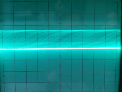
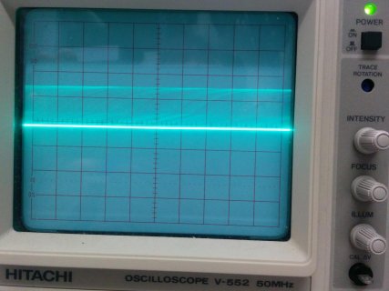
Neither of the chips is showing any sign of communication and when probing the Reset line from pin 8 of the Mini54 I get some weird noise on the scope:

IMG_20141112_115237.jpg


There is no change when I connect pin 20 (P5.2/Program push button) to ground. Any ideas what that might be?

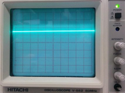
I'm pretty confident the crystal isn't interfering with this part of the circuit since power trace running under neath it looks OK on the scope:

IMG_20141112_113825.jpg


Presumably then there is an issue with the basic functionality of the Mini54, which would only be affected by power, ground or P5.2?

Many thanks!
 

Attachments

  • IMG_20141112_113815.jpg
    IMG_20141112_113815.jpg
    104.7 KB · Views: 181
Last edited:
How did you solder the min54? Make sure that you don't have any bridges or dry joints.

Also try and just power the Mini54 Programmer board and see if reset triggers when you press the prog button.
 
I can't say why your hardware isn't working, but from this photo, it seems pretty clear you need to adjust your oscilloscope's trigger threshold & holdoff settings.

Yes you're quite right sorry... It's actually a pulse from GND to +3v3 at an interval of ~56 uSecs, which is about 17.8KHz, ~1000 times slower than my crystal should be... Could this still be caused by the crystal do you think?

@johnnyfp - The mini54 does actually work when not attached to the rest of the board.. So it must be an issue with the main board.

My next step is going to be to cut the VCC trace running underneath the crystal and wire it straight to the mini54 board.

Thanks for your patience everyone...
 
aaaand IT WORKS! Turns out the problems were running VCC under the crystal along with the capacitance load settings for the crystal.

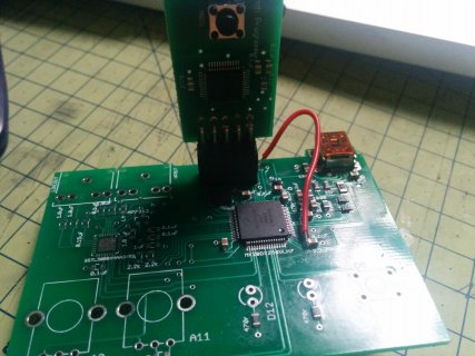
I rewired it like this:

IMG_20141115_114452.jpg

And changed the settings as Paul described, and I've got a blinking LED. Think I'll leave it a few days to enjoy the elation before testing the audio part of the circuit...

Thanks all!
 
Is there a way to change OSC0_CR for "series capacitance"? I messed up and got a 16MHz crystal with "Series" load capacitance..... :(

I looked at the ref manual, but not sure if not activating any of the internal caps would work or if that would create a whole new problem.
 
Last edited:
Is there a way to change OSC0_CR for "series capacitance"? I messed up and got a 16MHz crystal with "Series" load capacitance..... :(

I looked at the ref manual, but not sure if not activating any of the internal caps would work or if that would create a whole new problem.

I am designing a Teensy 3.1 PCB hybrid and am using a crystal resonator with 15pF internal capacitance,
CSTCE16M0V53-R0

If I change the line in the code here to read

// enable capacitors for crystal
//OSC0_CR = OSC_SC8P | OSC_SC2P;
OSC0_CR = OSC_SC8P | OSC_SC2P | OSC_SC16P ;

Will this work even though the load capacitance is actually 15pF and not 16pF?

It is a 2 layer PCB w/ ground plane under the resonator and center pin is grounded, others to XTAL/EXTAL

//from reference manual
SC16P
Oscillator 16 pF Capacitor Load Configure
Configures the oscillator load.
0 Disable the selection.
1 Add 16 pF capacitor to the oscillator load.
 
Correct me if I'm wrong (and I probably am!) - wouldn't using 8, 2, and 16 give you a 26pF capacitance and not 16? According to Paul, the pins themselves have about 7pF of capacitance just by existing, so you'd be at 19pF. I think you could probably drop the 2, and just use (8+16)-7 = 17. Or, (16+4+2)-7 = 15.

Ahhh, nevermind! My brainmath was all kinds of wrong.

You need double your capacitor's rating (so 30), then subtract 7 from that. So you want 23pF as your final value. In which case, why not just 8+16 = 24?

As a note, i've been using a 9pF crystal, with the default 8+2 settings, and it seems to be working fine.
 
Last edited:
I am designing a Teensy 3.1 PCB hybrid and am using a crystal resonator with 15pF internal capacitance,
CSTCE16M0V53-R0

If I change the line in the code here to read

// enable capacitors for crystal
//OSC0_CR = OSC_SC8P | OSC_SC2P;
OSC0_CR = OSC_SC8P | OSC_SC2P | OSC_SC16P ;

Will this work even though the load capacitance is actually 15pF and not 16pF?

It is a 2 layer PCB w/ ground plane under the resonator and center pin is grounded, others to XTAL/EXTAL

//from reference manual
SC16P
Oscillator 16 pF Capacitor Load Configure
Configures the oscillator load.
0 Disable the selection.
1 Add 16 pF capacitor to the oscillator load.

So will this work if I change it to :
// enable capacitors for crystal
OSC0_CR = OSC_SC8P | OSC_SC16P ;

//old code
//OSC0_CR = OSC_SC8P | OSC_SC2P;


I think I read that I would have problems if you use a crystal rated for more then 10 pF load capacitance
 
Status
Not open for further replies.
Back
Top