Teensy 3.1 and I2C

Status
Not open for further replies.

syntesys

Member
Hi to all.

I'm new on the forum!

I have problems with teensy 3.1 and I2C serial lcd adapter. The adapter has a PCF8574P mounted on it and I'm trying to execute a simple software thai initialize the lcd and prints the hello world. I'm using also LiquidCrystal_I2C 1.1 library.

I connected the gnd, VCC to Vin pin on teensy, sda and scl to A4 and A5 (they are correctly connected).

I don't know why, but when the code arrives to lcd.init(), the sketch doesn't continue (i put a blink before and after the init). The code works well on arduino.

So, what is the problem? I tried also with 4.7kohm pullup resistor from sda and scl to gnd but nothing. I tried also with 3.3v instead of 5v but nothing.

Can someone help me? Thank you.
 
You do need two pullup resistors, one from SDA to 3.3V and one from SCL to 3.3V. It sounds like you've already tried that, but perhaps try again (and do not try other ways on SCL and SDA, pullups absolutely are required).

If that doesn't solve the problem, perhaps post a photo of the actual wiring, a link to the specific display product, and the actual code you're trying. Specific and accurate details are important, so please be careful to post *exactly* what you're actually doing, not a casual but inaccurate description.
 
Yes, I tried with two resistors O
of 4.7 and also 10kohm but nothing. Tomorrow I'll take the photos and I'll link the LCD I2C.
Thank you.
 
Another thing that could be happening is your LCD needs 5v. A lot of the 16x2 and 20x4 LCDs require 5v rather than 3.3v. In this case, you will need to feed the LCD 5v of power, and level convert SDA/SCL to 5v as well. You can get bi-directional level converters for i2c at various locations, such as:


For i2c, I believe all can be used. I haven't used the current Sparkfun converter, but I have tried the other three and for the simple cases I tried, they worked for i2c. The Pololu and DSS converters can be used for ws2812 leds (neopixels) as well, while the Sparkfun and Adafruit converters aren't fast enough for ws2812 protocol.

Assuming you are powering the Teensy with 5v from USB, you would connect the VIN pin to the power line of the lcd, the grounds connected, and then wire up the converters so it converts SDA/SCL to/from 5v.

If you have a Teensy 3.1, you can try just using the VIN power to the LCD, but don't level convert SDA/SCL. It worked for me, but long term you are probably better off doing the level conversions.

The other thing to try is the alternate i2c library for the Teensy (http://forum.pjrc.com/threads/21680-New-I2C-library-for-Teensy3). The main problem with this library is you have to edit all of your sources and change Wire.h -> i2c_t3.h, because it is incompatible if both the standard Wire and the improved i2c_t3 are used in the same build.
 
Last edited:
Yes, I tried with two resistors O
of 4.7 and also 10kohm but nothing. Tomorrow I'll take the photos and I'll link the LCD I2C.
Thank you.
Just to make sure there is no misunderstanding.
The resistors need to go from SDA and SCL to +3.3V !!!NOT!!! FromSDA and SCL to GND
 
Another thing that could be happening is your LCD needs 5v. A lot of the 16x2 and 20x4 LCDs require 5v rather than 3.3v. In this case, you will need to feed the LCD 5v of power, and level convert SDA/SCL to 5v as well. You can get bi-directional level converters for i2c at various locations, such as:


For i2c, I believe all can be used. I haven't used the current Sparkfun converter, but I have tried the other three and for the simple cases I tried, they worked for i2c. The Pololu and DSS converters can be used for ws2812 leds (neopixels) as well, while the Sparkfun and Adafruit converters aren't fast enough for ws2812 protocol.

Assuming you are powering the Teensy with 5v from USB, you would connect the VIN pin to the power line of the lcd, the grounds connected, and then wire up the converters so it converts SDA/SCL to/from 5v.

If you have a Teensy 3.1, you can try just using the VIN power to the LCD, but don't level convert SDA/SCL. It worked for me, but long term you are probably better off doing the level conversions.

The other thing to try is the alternate i2c library for the Teensy (http://forum.pjrc.com/threads/21680-New-I2C-library-for-Teensy3). The main problem with this library is you have to edit all of your sources and change Wire.h -> i2c_t3.h, because it is incompatible if both the standard Wire and the improved i2c_t3 are used in the same build.

I read this in another 3d, but all threads speaks about teensy 3.0 and no usage of polulu level converter with 3.1.


Just to make sure there is no misunderstanding.
The resistors need to go from SDA and SCL to +3.3V !!!NOT!!! FromSDA and SCL to GND

Ok, maybe is this the problem, because I was putting the resistor from SDA to GND and SCL to GND. It's the same if I put the resistor from SDA to 5V? For the LCD, I'm using 5V.
 
I read this in another 3d, but all threads speaks about teensy 3.0 and no usage of polulu level converter with 3.1.
Some of the original threads pre-date the 3.1 launch, and Pololu only released the level converter a few months ago. For me, I was trying to save on space on my breadboard, and the Pololu adapter saves a few rows compared to 2 of the DSS converters (due to the DSS converters over-hanging a row on each side). For some things, I needed to convert both neopixels and i2c. The adafruit/sparcfun converters work fine for i2c, but not neopixels.

Ok, maybe is this the problem, because I was putting the resistor from SDA to GND and SCL to GND. It's the same if I put the resistor from SDA to 5V? For the LCD, I'm using 5V.
You want pull-up resistors. Pull-up resistors go between power and the pin, while pull-down resistors go between ground and the pin. For buttons/switches, you want want pull-down resistors, but i2c connections you want pull-up.
 
This is the adaptor I bought: LINK.

With arduino, it works well. I tried today with 4.7kohm resistor but nothing. I tried also with 10kohm but nothing. I tried with 1kohm and there is the surprise... Sometimes, the LCD is recognized. I don't know now if there is a cable problem (I'm using a 4-pin cable used with old CD Reader on tower PC). What do you think about it?
 
Following the link you provided I don't see any documentation for this device other than the description written in terrible English.
Would you have link to a schematic ?
 
I think at this point we need to see a picture of the complete wiring setup and the code that you use. Did you switch to using pull-up resistors (4.7K each for SDA/SCL, going between those pins and 3.3v power)?
 
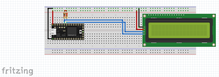
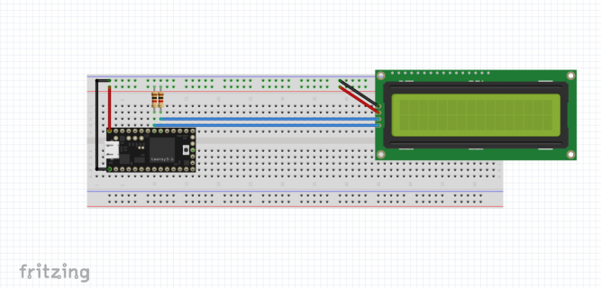
This is my circuit Circuit.PNG

For the LCD, I'm using 5 volts, not 3.3.
 
Last edited:
Hi syntesis.
Your circuit looks right to me.
To be precise, pullups may well be connected to 5V as you did since LCD and teensy are 5 Volt based or tolerant. I even prefer 5V because of better threshold margin of the signals.
In your picture the resistors do not look equal. Please check.
Maybe it is a good idea to unplug and reconnect all wiring using different holes to make sure there is no oxidated connection. Breadboards sometimes can play you a bad trick. If you have an electrolitic cap on your desk plug it in the 5v/GND rails just to make sure 5V is stable at the display.
 
Ops, I forgot to change the resistor value!

If i substitute teensy with arduino (using the same pins), it works well.
 
If it is wired as you say, and you don't have solder bridges or no connection, then you need to get a level converter or get a different LCD that works with 3.3v. Presumably, the LCD needs voltage closer to VIN (5v) to see a signal difference. I posted 4 such converters earlier in the thread.

Now, perhaps the LCD is 3.3v. If it is, switch the power pin from VIN to 3.3v on the Teensy. The 16x2 LCD I have will not work with 3.3v, but perhaps yours will.

<edit>
Another thing to look at is what library you are using to talk to the LCD. Make sure it uses Wire.h and not something else like i2c.h that some of the Adafruit code uses. In addition, look at the code, and see if it has an #ifdef in it. Some example code says if it is an AVR, use the Wire variable, and if the processor is ARM, use the Wire1 variable. Due to a poor design choice (IMHO), the Arduino Due tends to use the 2nd i2c port as the main i2c device, and example code assumes that if it isn't AVR it must be the Due. The Teensy 3.1 does have a second i2c bus, but it is inconvenient that pins 29/30 to use the bus are underneath the Teensy.
 
Last edited:
It certainly looks like it ought to work. But if it's not working, then something must be wrong. Several guesses have already been made, and really, guesses are all you're going to get with so little info posted.

Perhaps try posting an actual photo of your wiring, and a link to the documentation for the specific LCD you're using, and the exact code you're running on Teensy. We have a really good history of spotting problems when people do post such complete info. And sadly, threads like this which lack enough info to help tend to only waste everyone's time with wild guesswork.

Please, if you reply again, do yourself a favor and post enough information.
 
As I wrote on the first post, the adapter mounts a PCF8574P. Here and Here there are the datasheets of the module. The wiring is made on breadboard and is the same I made in fritzing; the unique difference is that I'm using THIS cable for connect the LDC to the breadboard. The library doesn't have problems, because with the pullups of 1Kohm I saw only one time the cursor blinking on the LCD (with Teensy 3.1) but the problem is that I can't reproduce it. So, the LCD works also with pullups, but it worked only one time.
 
Are you sure? Can you double check? Or try using 4 ordinary wires?

Those audio cables almost always have both black wires connected to the same shield, with only 2 conductors inside the actual cable.
 
Can you measure the DC voltage on the SDA and SCL lines (each with the multimeter's black lead connected to GND)? These would be the voltages actually on those pins, with everything connected and the software running, but not working.

Can you post a photo of how you've actually got this stuff connected?

I want to help you get this working. What's wrong is still a mystery. It's going to take some real measurements and maybe photos of what you're actually doing to figure out what's wrong.
 
Last edited:
I checked the cable and I've found that the cable is damaged.

EDIT: I tried with another cable but the situation is the same. I tried with another Teensy 3.1 and it works well. In the Teensy 3.1 I used before I saw that in the back there are two damaged gold plates... Can be this the problem of not-working LCD?
The tension on the two pins are the same in every board I tried (3.76V) so I don't understand...

EDIT 2: I don't know how, but I don't have still problems with LCD and the first Teensy... Yesterday I connected it and the LCD started to work without problems and without pullups resistors...
 
Last edited:
Status
Not open for further replies.
Back
Top