kig
Active member
Hello!
I for the FilxCapacitor project, I need to power both the Teensy 3.1 + audio shield, as well as the amp with two small 4Ohm speakers. I am using this amp: Stereo 2.8W Class D Audio Amplifier - TS2012 (https://www.adafruit.com/products/1552) from Adafruit, and these 2W speakers from Polulu: http://www.pololu.com/product/1258
My circuit has two separate SPST switches: One is for turning off all power (and sits right after the 5VDC power barrel), and one is for turning off the amp specifically. The reason I want this is so that I can turn off the amp completely and have speakers be completely silent, when not in use. Plus it will drain less power.
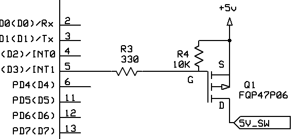
I am attaching a very simple circuit diagram (my first eagle drawing, so please don't be mean") )) to show how it's wired.
)) to show how it's wired.

My first question is: did I connect them correctly, meaning – is it OK for the amp's VCC/GND and Teensy VIN/GND to be directly connected (via a switch)? Do I need to isolate them from each other in any way? Do I need to put a diode to prevent "back current"?
The real problem is that right now when I am reloading BMP images on the TFT screen, I am hearing an audible effect through the speakers, whether or not the music is playing (as long as the Amp has power).
There are two additional parts that confuse/complicate things for me:
My second question is: I want the TFT display's LED not be always on. The instructions typically connect the LED to the VIN, which makes it on all the time. I want to control when I turn the display on/off programmatically, so I routed the LED connector to the digital pin #4, and setting it to HIGH. I am using a variable potentiometer (0-100Ohm), but I noticed that the brightness on the display was decreased significantly when I switch the LED from VIN to D4. Is that due to current limitation on the pins? Am I not doing this correctly? Should I drop the resistor to allow the LEDs be brighter?
Thanks so much for any help!
And Happy Thanksgiving!
I for the FilxCapacitor project, I need to power both the Teensy 3.1 + audio shield, as well as the amp with two small 4Ohm speakers. I am using this amp: Stereo 2.8W Class D Audio Amplifier - TS2012 (https://www.adafruit.com/products/1552) from Adafruit, and these 2W speakers from Polulu: http://www.pololu.com/product/1258
My circuit has two separate SPST switches: One is for turning off all power (and sits right after the 5VDC power barrel), and one is for turning off the amp specifically. The reason I want this is so that I can turn off the amp completely and have speakers be completely silent, when not in use. Plus it will drain less power.
I am attaching a very simple circuit diagram (my first eagle drawing, so please don't be mean
)) to show how it's wired.My first question is: did I connect them correctly, meaning – is it OK for the amp's VCC/GND and Teensy VIN/GND to be directly connected (via a switch)? Do I need to isolate them from each other in any way? Do I need to put a diode to prevent "back current"?
The real problem is that right now when I am reloading BMP images on the TFT screen, I am hearing an audible effect through the speakers, whether or not the music is playing (as long as the Amp has power).
There are two additional parts that confuse/complicate things for me:
- Amp has Left +/- and Right +/- for input signal, but I think that this "-" does not mean ground like it usually does. So I am NOT shorting "-" on the line input to the Amp's ground. Should I be?
- I have a 3V battery connected to Teensy supplying backup power for the clock. Just in case this matters
My second question is: I want the TFT display's LED not be always on. The instructions typically connect the LED to the VIN, which makes it on all the time. I want to control when I turn the display on/off programmatically, so I routed the LED connector to the digital pin #4, and setting it to HIGH. I am using a variable potentiometer (0-100Ohm), but I noticed that the brightness on the display was decreased significantly when I switch the LED from VIN to D4. Is that due to current limitation on the pins? Am I not doing this correctly? Should I drop the resistor to allow the LEDs be brighter?
Thanks so much for any help!
And Happy Thanksgiving!