Button To Run A File

Status
Not open for further replies.
but hey no i was thinking about something.. what if you connected Vin GRD TX RX to the TTL and used terminal or putty on the com port? would it find anything?

similar to this:

View attachment 3226

you would have to assign the pins to communicate with the TTL com port through Arduino? i'm not sure, just asking..
 
Last edited:
hey since i'm so fd up i wanted to share a soup recipe with you i came up with recently.. i call it Drowned

you need some weird sh!t from the asian market to pull this off
pot of boiling water, throw in some nori(seaweed paper like for sushi), onion, fish fillet, soy sauce, rice noodles, egg..

lol

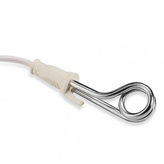
prison_soup_cooker.jpg
 
Last edited:
Teensy only supports reprogramming through the USB port.

Programming mode on Teensy is NOT like Arduino. Teensy does NOT use serial protocol at all while programming. In programming mode, Teensy appear as a USB HID device with ID 16C0:0478. It is not a serial port in any way when programming.

Teensy 3.1 has 3 hardware serial ports. None of them are supported for reprogramming Teensy. But when your code is running, you can access them as Serial1, Serial2 and Serial3.
 
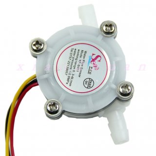
Specs - looks like a pulsed output, 5V, hall-effect sensor, as follows

Frequency: F = 98 * Q (Q is flow L / min) error: ± 5 stream End liters of water output 5880 pulse

Frequency calculation = constant * unit flow (L / min) * time (seconds)

Flow Range :0.3-6L / min


=======
@josh: Now in consideration of my 2 minutes of Google work for you, I ask only that you not use the pseudo-profanity style in postings.
 
Last edited:
steve sorry i think i know what youre talking .. i get a little carried away but yes i want to stay focused..

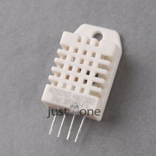
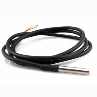
okay, i bought a temp probe and a humidity sensor for like 2 bucks a piece.. i'm thinking they sent me stuff that is already broken but could someone please verify that i'm doing this correctly..

http://www.ebay.com/itm/371197517453

12.JPG

http://www.ebay.com/itm/331111738688

1221.JPG


my question is shouldn't i just use serial input.. i was using this:

void setup()
{
Serial.begin(38400);
}

void loop()
{
val = analogRead(A9);
Serial.print("analog is: ");
Serial.println(val);
delay(250);
}


i was only testing the sensors so just using serial monitor the output is 1023 on the humidity sensor.. the temp probe reads the same now.. they don't obviously increase beyond 1024.. any ideas? thanks
 
void setup()
{
Serial.begin(38400);
}

void loop()
{
val = analogRead(A9);
Serial.print("analog is: ");
Serial.println(val);
delay(250);
}

In setup() you need pinMode(A9, INPUT). Unlike regular AVRs where all pins default to input on boot, the pins on a Teensy 3 default to 'disabled'. You have to explicitly say they're going to be used for input.
 
i'm getting data but it's not mirroring the temp change.. when i disconnect the data pin the value is a lot higher than with the sensor connected.. shouldn't it read zero with nothing connect to the pin?

i added that to the setup, thanks ptron!

right now its:


void setup() {
Serial.begin(38400);
pinMode(14,OUTPUT);
digitalWrite(14,HIGH);
pinMode(22,OUTPUT);
digitalWrite(22,LOW);
pinMode(16,INPUT);
}

int GGG;

void loop()
{
GGG = analogRead(16,INPUT);
Serial.print("analog is: ");
Serial.println(GGG);
delay(900);
}
 
i should say i'm getting a constant value of 211 with the sensor connect and if i disconnect the analog pin it reads 800
 
i mean shouldn't it be a smaller value with the pin disconnected, not necessarily zero but why would it be like wide open with nothing on it?
 
the pin makes voltage and the pin reads voltage.. what's it doing making voltage or reading voltage?
 
Sorry if I'm missing something but I'm on my phone and can't really see -- are you using the first temp probe (the white one with 4 pins) or the second one (the silver one with wires) ? Can you please let me know how it's all connected?
 
the pin makes voltage and the pin reads voltage.. what's it doing making voltage or reading voltage?

The analog input pins are extremely sensitive.

When the pin is disconnected, almost anything can influence the voltage at the pin. Nearby signals, electo-static coupling (similar to how a balloon can stick to a wall after being rubbed across fabric), magnetic coupling to the large AC currents powering nearby lights, computers or machinery, or all sorts of other minor effects are very capable of influencing the voltage at the pin. Typically, unconnected pins tend to read some random number that changes slowly in value. But almost anything is possible with the pin unconnected.

The point is almost anything can be "making voltage" at the pin when it's disconnected. It's a very high impedance, meaning it's able to be easily influenced by almost anything.

Internally, what's "reading voltage" is called a capacitive redistribution successive approximation analog to digital converter.

The heart of it is a voltage comparator, which uses a pair of very closely matched transistors to compare 2 voltages, telling which is higher than the other. In digital circuits, transistors are operated either completely turned off, or turned on as fully as possible. But in a comparator, other special circuitry causes a fixed current to flow through both of those transistors, but it doesn't control how much of the current each transistor uses. The transistors are operated in a partially conducting state. Even a very tiny change of voltage at the input can cause either transistor to sway how much of the current flows through each transistor. In mosfet transistors, the input is to a "gate" which is conductive material suspected extremely close to the silicon underneath, where the voltage on the gate can influence the current flow in the material underneath. Other circuitry in the voltage comparator further processes the currents from those 2 transistors, turning it into a digital signal which indicates which transistor had higher voltage. Fundamentally, this voltage comparator circuit is the only thing actually measuring the voltage.

The "successive approximation" part is similar to the number guessing game, or a "binary search" in computer science lingo. For example, I'm thinking of a number between 1 to 100. You guess 50. I saw it's higher. Then you guess 75. I say it's lower, and then you guess 63, and so on. The key component is the voltage comparator circuit. That's what tells you if the guess is higher or lower than the actual signal.

The guessing game part is done with "capacitive redistribution". Inside the chip are some capacitors, formed by very closely spaced layers of conductive material suspended just above the silicon. The important point to understand about capacitors is their voltage is proportional to the charge, or number of electrons, physically present on the material. When there's double the number of electrons, the voltage is double. That's simply how the laws of physics works for electrons (and good quality material between the conductive surfaces).

When you have 2 capacitors with different voltage and you connect them together, charge will automatically flow between them, causing their voltage to equalize. The happens because charged particles repel each other, and they're attracted to oppositely charged particles. When connected, the side that has more electrons will push some of its electrons away. Both sides have a net positive charge on the other side of their insulating material which also attracts the electrons. These force cause the voltage of 2 connected capacitors to always equalize, in the absence of other forces trying to change the voltage (by pushing more electrons in or pulling them away).

Capacitive redistribution is simply using this capacitor charge/voltage sharing to divide voltages in half. Transistors are used as switches, to sometimes connect the capacitors together. But sometimes, other transistors are used to short one of the capacitors, draining off all its charge and clearing its voltage to zero.

If the comparator indicates the guess is too high, it's 2 capacitors holding the guess are separated and one is drained to zero. When they're reconnected, the guess becomes exactly half the original voltage. Likewise, the original signal gets captured onto capacitors. During the successive approximation guessing, some crafty digital logic implements the guessing game by sometimes halving the reference voltage (what is considered the maximum level) and sometimes the signal voltage. Then it guesses again, just like you would in the guessing game. Each guess produces another bit of the numerical output, until it's fully converted the signal into the binary number you get.

Actually designing these capacitive redistribution successive approximation analog to digital converters involves some pretty tough challenges. Digital switching of the transistors can inject tiny extra charges onto the capacitors, leading to errors. The pairs of capacitors need to be very precisely matched, and stay matched even if the chip changes temperature, and even if there's a temperature difference/gradient from one side of the chip to another. The voltage comparator also has a number of design challenges, especially in trade-offs between its internal power consumption and the speed at which it can detect tiny changes, which ultimately imposes a speed limit on how quickly the entire ADC can convert your voltage to a number. Thermal noise is always an issue in all analog circuits. Fortunately, these types of converters have been in widespread use for about 20 years. The various semiconductor manufacturers have refined them very well.

That's probably more than you ever would want to know about what's inside the chip, but you did ask how it's reading voltage. ;)
 
Last edited:
that is very interesting..

i'm hooking them up the same way, the humitidty sensor only uses 3 of the four pins, the temperature probe has three wires.. v+, gnd-, data..

humidity sensor:
http://www.adafruit.com/datasheets/Digital humidity and temperature sensor AM2302.pdf

temperature probe:
http://dlnmh9ip6v2uc.cloudfront.net/datasheets/Sensors/Temp/DS18B20.pdf


i have been unable to see a fluctuating value in arduino serial monitor.. i'm basically hooking it up the same way as the thermistor in the tutorial except just hooking up the data wire to the analog pin.. i might be missing something since the thermistor only has 2 leeds do i need to put the gnd or v+ in the circuit with the data wire somehow? thanks for all the help
 
First post on these forums, so... Hello, world! :D
A quick glance at the PDFs shows that both sensors are digital, i.e. should be connected to a digital pin.
i have been unable to see a fluctuating value in arduino serial monitor.. i'm basically hooking it up the same way as the thermistor in the tutorial except just hooking up the data wire to the analog pin
As said, they are digital. They have their own on-board processing and their output is digital data. You connect them to power, ground and a digital pin, issue commands to them and they respond with digital data values.
i might be missing something since the thermistor only has 2 leads do i need to put the gnd or v+ in the circuit with the data wire somehow? thanks for all the help
Both sensors have a Vdd pin/lead that should be connected to power. The temp sensor's Vdd lead can be connected to gnd, in which case it will derive the power it needs from the data wire.

I found an example in the Arduino program for the temp sensor.
temp_sensor_example.png
I'm not sure about the other, but there seems to be an Aurduino library for it: http://playground.arduino.cc/Main/DHTLib

Caveat, I don't have any personal experience of any of the sensors. I've have just looked through the data sheets.
--
Ragnar
 
hey on the Onewire code do you have to tell it the device address??

#include <OneWire.h>

/* DS18S20 Temperature chip i/o */

OneWire ds(10); // on pin 10

void setup(void) {
Serial.begin(9600);
}

void loop(void) {
byte i;
byte present = 0;
byte data[12];
byte addr[8];

if ( !ds.search(addr <<<<<<---HERE?------>>>>> )) {
Serial.print("No more addresses.\n");
ds.reset_search();
delay(250);
return;
}

it's just returning "no more addresses" but nothing after that
 
Last edited:
You can give it the address, which avoids the need for the search. But the search works just as well, using a little more time and communication.

If the search isn't finding your sensor, you almost certainly have a hardware problem.
 
okay cool.. i'm still fooling around with it.. i don't have a 4.7K resistor.. i used a 2 2Ks and a 510 and a 150 in series.. i wonder if thats it..
 
okay cool.. i'm still fooling around with it.. i don't have a 4.7K resistor.. i used a 2 2Ks and a 510 and a 150 in series.. i wonder if thats it..

That should work, but if you have a multimeter make sure it's around that value and that there's no short anywhere.
 
hey again I need help. I finally got the flow sensor i mentioned above and started messing around but can't make it work.

i tried this code:

// reading liquid flow rate using Seeeduino and Water Flow Sensor from Seeedstudio.com
// Code adapted by Charles Gantt from PC Fan RPM code written by Crenn @thebestcasescenario.com
// http:/themakersworkbench.com http://thebestcasescenario.com http://seeedstudio.com

volatile int NbTopsFan; //measuring the rising edges of the signal
int Calc;
int hallsensor = 2; //The pin location of the sensor

void rpm () //This is the function that the interupt calls
{
NbTopsFan++; //This function measures the rising and falling edge of the hall effect sensors signal
}

// The setup() method runs once, when the sketch starts
void setup() //

{
pinMode(hallsensor, INPUT); //initializes digital pin 2 as an input
Serial.begin(9600); //This is the setup function where the serial port is initialised,
attachInterrupt(0, rpm, RISING); //and the interrupt is attached
}

// the loop() method runs over and over again,
// as long as the Arduino has power

void loop ()
{
NbTopsFan = 0; //Set NbTops to 0 ready for calculations
sei(); //Enables interrupts
delay (1000); //Wait 1 second
cli(); //Disable interrupts
Calc = (NbTopsFan * 60 / 5.5); //(Pulse frequency x 60) / 5.5Q, = flow rate in L/hour
Serial.print (Calc, DEC); //Prints the number calculated above
Serial.print (" L/hour\r\n"); //Prints "L/hour" and returns a new line
}


and i tried this code:


/*
YF-S201 Hall Effect Water Flow Meter / Sensor
http://www.hobbytronics.co.uk/yf-s201-water-flow-meter
Read Water Flow Meter and output reading in litres/hour
*/

volatile int flow_frequency; // Measures flow meter pulses
unsigned int l_hour; // Calculated litres/hour
unsigned char flowmeter = 2; // Flow Meter Pin number
unsigned long currentTime;
unsigned long cloopTime;

void flow () // Interruot function
{
flow_frequency++;
}

void setup()
{
pinMode(flowmeter, INPUT);
Serial.begin(9600);
attachInterrupt(0, flow, RISING); // Setup Interrupt
// see http://arduino.cc/en/Reference/attachInterrupt
sei(); // Enable interrupts
currentTime = millis();
cloopTime = currentTime;
}

void loop ()
{
currentTime = millis();
// Every second, calculate and print litres/hour
if(currentTime >= (cloopTime + 1000))
{
cloopTime = currentTime; // Updates cloopTime
// Pulse frequency (Hz) = 7.5Q, Q is flow rate in L/min. (Results in +/- 3% range)
l_hour = (flow_frequency * 60 / 7.5); // (Pulse frequency x 60 min) / 7.5Q = flow rate in L/hour
flow_frequency = 0; // Reset Counter
Serial.print(l_hour, DEC); // Print litres/hour
Serial.println(" L/hour");
}
}


It's a YF-S401 Flow Sensor. I used a 10K pullup resistor between V+ and Sig.. I have no idea if this should work, I get no errors only a repeating "0 L/h"in the serial monitor. Thank you for any suggestions.
 
Last edited:
Status
Not open for further replies.
Back
Top