Q: I think i bungled flying capacitor implementation. Advice? Schematic attached

Status
Not open for further replies.

Tomek

Well-known member
So a few months back I made a PCB board for testing some higher voltages with my teensy. (9 voltages from +/- 0-36V in ~4v increments with a voltage divider for the final 4v output into a teensy analog input.)

I got the idea from a forum member to do this via flying/floating capacitor measurements even longer ago:
Original Thread:
Explicitly about flying cap thread (2nd thread):

I finally got to populate my board, write some code, and test out the circuit...but after some basic initial problems, and testing the SSRs to make sure they opened fully, I think I realized I made a grave mistake...

It looks to me that I set up a situation where I properly float my capacitor and connect it to the voltages I want to measure, but when I go to measure the voltage (after disconnecting from my sources) I put one leg of my cap at the analogInput, and the next leg........floating!!

So, I think that is why I'm not successfully measuring anything.
I can't attest to why I made my original schematic as I did, but I think I did it completely foolishly. [edit:I looked at the thread from before! It looks like originally in my proto-schematic I posted there, I was not stupidly floating the capacitor. So somewhere along the line I broke the plan and forgot to question the logic.]

finally, purpose of this thread / TL;DR I was hoping I could show two partial schematics, (1) what I made . And (2) what I think I should have made. Any comment on the idea that the 1st is wrong, or the 2nd improved, would be greatly appreciated.
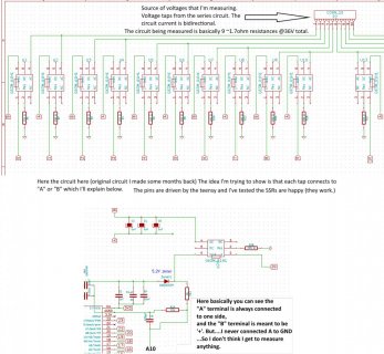
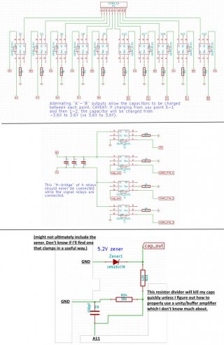
OriginalCircuit.jpg
FixedCircuit.jpg


[ADDENDUM Just some opamp questions, not too important compared to the first part.]
I've spent several hours trying to read about op-amps type devices, but I'm not entirely sure what I'm doing. The final voltage from my capacitors will be ~4V, a bit too high for the teensy. At the moment I'm using a 6k:10k ladder/divider, but that will quickly discharge my 3uF flying storage cap and I don't really know if I can read the voltage fast enough (I also have to give some time to ensure the SSR is opened fully.) If I slow the discharge with a higher resistance ladder/divider, I increase the impedance, which is another topic I don't fully know much about with respect to how it'll affect the ADC.

I think this means I need a buffer amplifier. But from what I read there are alot of opamps and I'm not clear on what will skew my data since usually the op-amps seem to be used for amplifying applications. SO, erm, are there go-to high-accuracy (<0.5% distortion from the signal) buffer amps that I should be looking at? I don't expect my hours of non ECE reading to get me to understand them so well, but I'm hoping I might get a practical idea of how to implement one without massive error. And I guess since I'll need a >4V power source for the amplifier, anything fancy I need to do for the power source? Does it have to be a linear regulator or can I just use a 5V step-down switching regulator from Pololu or somewhere?


Many thanks, [seriously, many thanks. i am looking around a lot and hoping to learn more, but sometimes reach a roadblock on what I can read about without just asking.]
-Tomek
 
For your opamp question -- you need to use an opamp configured in unity gain (output connected directly to the inverting ('-') input, and connect the flying cap to the non-inverting ('+') input. At the output connect your 6k:10k and drive the Teensy.

The opamp just needs a supply >= 4 V -- the 5 V that powers Teensy from USB is OK.

The opamp parameters you care about are DC offset (typically in mV); input bias current; and rail-rail inputs and outputs (so it can handle signals that approach the supply rail). This may be suitable - http://www.ti.com/lit/ds/symlink/tlv342a.pdf. So would this - http://www.maximintegrated.com/en/datasheet/index.mvp/id/1267/part/MAX492 and it is available in a DIP.
 
Thanks jp3141!

I think I was getting overwhelmed with the info on opamps (they have alot of what seem to me subtle parameters). I'll look at the two you suggested and individually read up on each term you mentioned. Thank you.
 
I also am looking at what I did before and increasingly confident that i messed up my current board by not connecting the one leg of the capacitor to anything when i tried to measure the other leg.
 
For your opamp question -- you need to use an opamp configured in unity gain (output connected directly to the inverting ('-') input, and connect the flying cap to the non-inverting ('+') input. At the output connect your 6k:10k and drive the Teensy.

The opamp just needs a supply >= 4 V -- the 5 V that powers Teensy from USB is OK.

The opamp parameters you care about are DC offset (typically in mV); input bias current; and rail-rail inputs and outputs (so it can handle signals that approach the supply rail). This may be suitable - http://www.ti.com/lit/ds/symlink/tlv342a.pdf. So would this - http://www.maximintegrated.com/en/datasheet/index.mvp/id/1267/part/MAX492 and it is available in a DIP.

Hi JP again! (or anyone else reading.)

So I've read a bit more, and went off base for a while trying to determine if I want an in-amp or op-amp. The in-amps sound cooler (well of course! they are basically 3 op-amps) but practically seem to be used for other things. So I appreciate your links guiding me towards simple rail-to-rail op-amps.
Unfortunately to try and understand in vs op amp, I've even read even this: http://electronicdesign.com/power/w...nal-amplifiers-and-instrumentation-amplifiers, and am still some way from differentiating between the amplifiers. I know I can be really slow to understand things I'm not emphatically interested in (practically I'd like to know something, though.)

OK, back to focus on the two links you suggested me: [btw I appreciate the DIP suggest and while I'll often use DIP if I can I also pretty much find reasonably-sized non-tiny SMD to be as easy for me to use as DIP. I hand soldered my last SMD board but I bought a $10 target hot-plate I'll try to reflow with next time. Hand-soldering allowed/caused me to jitter the part placements with my hand sometimes.]

TLV342A:
rail-to-rail (yay)
5.5V max
1pA-100pA bias current (ok! tiny, even for only 3uF of storage.)
Input voltage offset = 0.3mV, so O-K for my application esp after calibration and within the range of indoor temperatures. Further examination says 0.3mV-4mV max, but I'll get the "A grade" kind so I have only 1.25mV maxinum.
slew rate = 0.9V/uS, my application doesn't care much about slew rate I'm sure that will be fine [I have to wait 0.5mS to be sure the switches are open anyway.]
The parts besides the chip that I'll need I think are just:
200pF cap for output [IDK, it was on a circuit in the datasheet. I could ignore it if it's just for stability and use the cap on the voltage divider for stability of measurement.]
For Unity gain I think I just need the output be referenced to the inverting input? This sounds awesomely simple and I hope is the case. No resistors?

Question is there any reason you linked to the 342A instead of the 341? The 342 is a dual op-amp and the 341 is a single op-amp, but I think I only really need 1 op-amp. Could just be the way the URL shows, and not really intentional on your part. I think I'll be looking for the 341A unless I can figure out why I'd want the 342A.


OK: MAX492: [2 is the dual-opamp, apparently 5 was discontinued because some other wafer company made shitty chips for maxim by the sounds of it]
rail-to-rail
Marketing says "unity gain stable" which I have no idea what it means but sounds like something I want.
6V [this is a pro over the TI, I like slightly more leeway on what max voltage I can do.]
Input-offset 0.2mV-0.5mV (ooh, better than the TI)
Bias current 25-60nA, somewhat higher, and hopefully not a problem, but suddenly something to think about.

QuestionOk, looks like the pros and cons of the two are:
PRO TI:
1-100pA bias current! Great for my 3uF caps
PRO MAX492:
6V range!
less input voltage offset. (max 1.2mV vs 4mV)
potentially dangerous 20-60nA input current bias. I think this might be almost a problem for the 3uF caps,if I'm reading the datasheet value correctly.

So I have to make a choice. Might go towards the tlv2461A simply because I can acquire it more easily :), and they both seem suitable enough.


I don't actually have USB power on my application, and I'm just using a 3.3V DC-DC switching regulator. But since I'm running constant serial information maybe I should use the USB power, and get some dedicated aRef for measurement. Ooph, so much to do. But I can easily add a 5V linear regulator from my 36V source for the miniscule currents of the op-amp.

Just a thought: I might not actually need a rail-to-rail op-amp. If I'm throwing in a linear regulator dedicated for the opamp, and I have 36V source, if I had something less than rail-to-rail but which had a higher input voltage like 8V, then I would also be OK.
I made the mistake of just looking at TI's precision opamps, and reducing someone the newly-learned parameters (<0.1mA, <5mV offset, >4V vin, etc), but was pretty quickly overwhelmed (still 108 results haha!). Plus I think I was looking at the wrong parameter (Iq per channel i thought meant input bias current but looks more like operational current bc I found a lot of battery optimized results.)

I redid the parameters to find amplifiers better than the TLV2461A in several categories, but still found 301 results this time, so I am giving up and going for the lovely TLV2461A incase there's a problem with any of the other ones I looked at :p.
But just for fun I'll note OPA377 looked pretty good, in fact probably better than the TLV2461A. And cheap. I just don't want to overlook any important parameter I may have noticed (except that it can source a little less current than the TLV2461A --> 30mA vs 40mA.
 
Last edited:
I didn't pick the dual opamp for any specific reason -- just that was the easiest link to grab. My point was more to show you the parameters that would be of interest, not specifically to find the 'best' opamp for this circuit.

60 nA on 3 uF will cause voltage droop of dV= deltaT.I/C; so in 1 ms, you'd get a droop of 1m*60n/3u = 20 uV -- likely not really a problem (and consider what leakage the switches will have, and leakage on your PC board).

You're right about not needing rail-rail if you have a higer V supply available.

Unity gain stable means it will work in a buffer configuration like you need. Most opamps are unity gain stable.

An instrumentation amp (INA) is more complex; it is used if you need to measure a differential signal (i.e. where one end is not referenced to GND).
 
Last edited:
I didn't pick the dual opamp for any specific reason -- just that was the easiest link to grab. My point was more to show you the parameters that would be of interest, not specifically to find the 'best' opamp for this circuit.

60 nA on 3 uF will cause voltage droop of dV= deltaT.I/C; so in 1 ms, you'd get a droop of 1m*60n/3u = 20 uV -- likely not really a problem (and consider what leakage the sitched will have, and leakage on your PC board).

You're right about not needing rail-rail if you have a higher V supply available.

Unity gain stable means it will work in a buffer configuration like you need. Most opamps are unity gain stable.

An instrumentation amp (INA) is more complex; it is used if you need to measure a differential signal (i.e. where one end is not referenced to GND).

Thanks JP, and I think going through the specific parameters you pointed out to me was helpful for me to get an understanding of the individual parameters. That is, when I was looking at everything at once I was very confused but the specific parameters you pointed out were relevant and more obvious (taken piecewise.)

I must have made a mistake with the zeros when I calculated the 60nA case, because I got a magnitude higher loss- but your check is completely correct I think. Anyhow, I think I have a better idea what to do with the op-amp, thank you.

And, ah, yeah, I was seeing all the use-case examples for in-amps to be wheatstone bridges and the like. I'm sure there are many more but I guess the purpose is more specific. I feel comfortable now choosing an opamp; thank you!

Right now I do have one remaining parameter I am looking at:
I am not sure if I am "allowed" to do something with respect to the floating capacitor. So I have this capacitor, and I connect one leg to ground occasionally. Can I first connect that leg to a 20Ohm resistor and then ground? I'm not entirely sure what the effect of that would be, and I usually see capacitors connected directly to ground. I'm thinking maybe I would be limiting the out-flow from the capacitor as if it had higher ESR, but I think that wouldn't matter for this case much (going into an op-amp.)

My purpose for this would be so that rather than charging the capacitors from the previous "-4V" to "4V" [as my current schematic would need to do once per measurement set] i could charge discharge both legs through ground by the same SSRs that allow me to un-float my capacitor for the measuring time. The issue is that I would need a 20 ohm resistor to prevent the theoretical peak current from damaging the SSR.
Not sure if that's the kind of question you'd know about (or if it was phrased clearly enough.)
 
Yes, if the SSR could be damaged by discharging (or charging) a capacitor, a R in series would protect it by limiting current.

What SSR are you using ? If these are mechanical (e.g. reed relays), then a R is absolutely necessary. If it is a solid-state one, it may not be really needed.
 
Yes, if the SSR could be damaged by discharging (or charging) a capacitor, a R in series would protect it by limiting current.

What SSR are you using ? If these are mechanical (e.g. reed relays), then a R is absolutely necessary. If it is a solid-state one, it may not be really needed.


I was going to go with an affordable OMRON SSR switch with 25Ohm on resistance:http://www.farnell.com/datasheets/1319812.pdf
But the datasheet I could find only specified continuous current (70mA.)

I found a similar priced Vishay switch (http://octopart.com/partsearch#!?q=VO1400AEFTR) which I liked more because their datasheet had a specification for max peak current (350mA.) Luckily peak current can be calculated, and because the switch doesn't turn on with minimal resistance instantly I think that actually helps me to slow down the current into the caps (i.e, ideal calculation for max current > real situation = some safety margin in the calcs.)
The only downside I see of the Vishay switch is that it has worse tolerance on the forward voltage of the on-switching LED (0.6V vs 0.3V ranges), but it's still easy to choose a resistor that works for the full potential range.)

But even with 5 Ohm resistance that the second part has, I would exceed the 350mA max current. So I added 20 Ohm resistors to protect charging the caps from the voltage taps. Then I'll be well within the max current and the whole thing would still take <0.5mS to charge the 3uF caps from what I remember when i was fiddling with some cap charge calculators earlier today.

I could just add 40 Ohm resistors to protect charging for the worse case of going from -4V to 4V. But I'd rather use the fact that each leg of the 3uF capacitor has to be switchable to ground to un-float the capacitor, and use this fact that I have that part of the circuit required, to simply turn both legs to GND when I want to discharge from -3.6-0V, and so that I can charge again from 0V to 3.6V. This is a minimally important idea but I think would be "better" and I would feel more satisfied. Another solution would be to size my current limiting resistor to account for the worst case of -4V --> 4V charging but I think that's a crummy solution because it technically slows all the measurement down (but not too much.)

The part I'm floppy about with respect to the logic/actual electrical knowledge, is whether or not a 20 Ohm resistor from leg A or B of the cap to ground would interfere with the main purpose of switching the capacitor to ground, which is to make that plate charged with respect to ground (i.e, to un-float the capacitor.) I *think* it would slow the speed at which the capacitor could discharge (ESR?), but since my cap is not being used for that purpose, I don't think it would negatively affect the de-floating/un-floating purposes.

Summary:

Current I have (VOLTAGE)--->---(SWITCH)--->CAP_LEG --->(SWITCH)----> ??? ---> GND. And the uncertainty is whether adding a 20-ohm resistor at ??? would make it a problem to unfloat the capacitor.


EDIT: I think I understand why I'm having trouble being comfortable with this. Somehow to me it is intuitive to imagine the "positive" lead of a capacitor discharging into a resistor. So long as not much current is flowing, the point you test at is still sitting at, say "5V" (if the cap was 5V) even though there is a, say, 20 Ohm resistor between the cap lead and the part of the circuit you're testing at.

But for some reason I was very tripped up by the idea that the "negative" leg of the capacitor could also be attached to ground through a 20 Ohm resistor in much the same way. I think it would be the same thing, really. But I am/was uncomfortable with it or at least uncertain enough to feel the need to ask.
 
Last edited:
Either of those SSRs will be OK discharging a 3 uF from 4 V without a separate external resistor. The limits are continuous limits for power dissipation, not transient.

Note the Omron SSR has a possible leakage current of 1000 nA -- much worse than the opamp; in practice, at room temperature it will be closer to the 1 nA typical value though.

The cap doesn't care which end has the resistor. The voltage approaches its final value with an exponential decay. Using 10 time constants (R*C) gives plenty of margin. Note that the SSR also takes nearly 1 ms to switch.

I'm possibly nitpicking, but I'm actually concerned that the SSR might not be OK with the theoretical peak current. Can you explain why they would be?

According to this calculator with a R of 5 ohms, going from 0 to 4uF, and pretending the capacitors (film capacitors) are zero ESR, I could get 800mA peak current. http://mustcalculate.com/electronic...rge.php?vfrom=0&vto=3.999&vs=4&c=.0000045&r=5

Which for the vishay's which are the only one rated, is above their peak current rating (350mA.) I guess is the impulse rating for the SSR defined for a larger peak than what I'm looking at? The thing is I read some scary app note basically saying "you can get away with peak currents but they'll cause minute metal migration over time and wear out the SSR"
 
In these types of devices the rating is for guaranteed high reliability and high stress use over a long time and at elevated temperatures. I suspect you are only operating at 'reasonable' temperatures, and don't need reliability the same as a manufacturer of (say) 100,000 devices would need.

In addition, your transient pulse current would only last 3u*5Ω=60 us which is very short (and the duration where the current exceeds the limit is much less than this); also the SSR takes ~ 1 ms to turn on, and the SSR's switch resistance is 20 ohm anyway, so the actual observed peak currents would be less than 4V/5ohm.

Although not directly comparable, look at Omron's LED peak current rating vs. the DC rating (1 A vs. 50 mA). There is a similar over current capability for the switch portion of the

Thanks Jp! The LED peak current vs DC rating was a good illustrated analogy. I appreciate the practical advice, as I don't have much experience. I am definitively not needing the real production reliability and just want to be within the scope of not having to chase problems when I put together my board or a month or two down the line (I mean, I doubt these things will see more than 5,000 switch events in their lifetime before I lose the PCB even if I keep measuring frequently and for a while.)

As it stands I ordered the board with 20 ohm resistors earlier today from OSHpark because I really wanted to rush out the changes because I felt a bit stupid i screwed up the first board (and after populating like $50 in parts :'( ). I might keep them or just short the 1206 pads. The SSR I ended up choosing (the vishay one) looked a bit better. I'm fairly confident as you say the peak current will not be crazy. Neither can by 1.7Ohm source voltage deliver the current instantly, nor will it flow through the SSR instantly, and so the whole thing should be much less bad than the calculator suggested.

Almost messed up my board though, at one point in my schematic I connected with a global tag "36V" and elsewhere I wrote "V36" so it did not connect on my PCB board :'(. But hesitated before pressing pay to look over *one more time* when that showed up. Anyway, I ramble, quite extensively.

Thanks again for all your help and feedback.


By the way: a kind of cool test would be to make a board to just cycle the SSR for ages at 0.1% duty cycle so it wouldnt heat up but would still get wayyyy more activity than my tests will require. Too bad there is not infinite time to try stuff like that. I remember reading a cool blog post where someone tested out the avr 328p EEPROM and he didn't find errors until 20x+ the rated cycle count. Slightly different issue though (I guess eeprom wears out because of high voltages generating brief high currents, so I guess maybe their failure is not too dissimilar to that of a very briefly peak-current treated SSR over cycle counts.)
 
Status
Not open for further replies.
Back
Top