Hi,
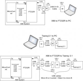
I am attempting to drive Teensy3.1 with a (x86 micro plus FT232R) system.
On the x86 I have serial read/write that appears to work with x86<->FT232R<-USB cable->Win_7_PC
On Teensy 3.1 I have the usb_serial example running, with Teensy3.1<-same USB cable->Win_7_PC working.
I check both the x86 and Teensy3.1 connectivity on PC using puTTy with appropriate COM port.
However when I connect x86 <- USB cable -> Teensy3.1 , I have no communication between them.
I modified the usb_serial example program as listed below. I notice that when the
Teensy3.1<-USb cable-> PC is connected, the program waits in "!Serial.dtr()" while loop.
When I start puTTy on PC, then Teensy3.1 starts to respond (type o to turn LED ON, f for OFF etc).
However when I plug in same cable to x86<->FT232R<- USB from Teensy3.1,
again I see that Teensy3.1 is waiting in loop "!Serial.dtr()".
Seems both the x86 system and Teensy3.1 are working fine on their own. But what
could be the problem?
Thanks in advance,
//////////////////////////////Serial_test.ino///////////
const int ledPin = 13;
void setup()
{
Serial.begin(9600);
pinMode(ledPin, OUTPUT);
}
void loop()
{
char incomingByte;
while (Serial.available()) {
incomingByte = Serial.read(); // will not be -1
if(incomingByte == '\n'){ Serial.print(incomingByte);}
if(incomingByte == 'o') { Serial.print(incomingByte); digitalWrite(ledPin, HIGH);}
if(incomingByte == 'f') { Serial.print(incomingByte); digitalWrite(ledPin, LOW);}
Serial.println("Hello World ** \n\n");
}
while (!Serial.dtr()) {
digitalWrite(ledPin, HIGH);
delay(250);
digitalWrite(ledPin, LOW);
delay(250);
} // wait for user to start the serial monitor
}
///////////////////


