I am moving a bit of code from an ATmega328P Arduino to the Teensy 3.1. I do a fair amount of bit banging by directly manipulating the GPIO ports rather than using digitalWrite calls. The Teensy reference card lists the GPIO pins as pin numbers so I went to the schematic to see what the corresponding GPIO designations are. As an example:
What is surprising (to me) is that my code runs fine without modifications. Pin 3 still looks like PortD3 and not PortA13(!)
What are the port designators for the Teensy 3.1? The digital I/O table doesn't list the 3.1 https://www.pjrc.com/teensy/td_digital.html
Additionally what are the meaning of the designators on the schematic?
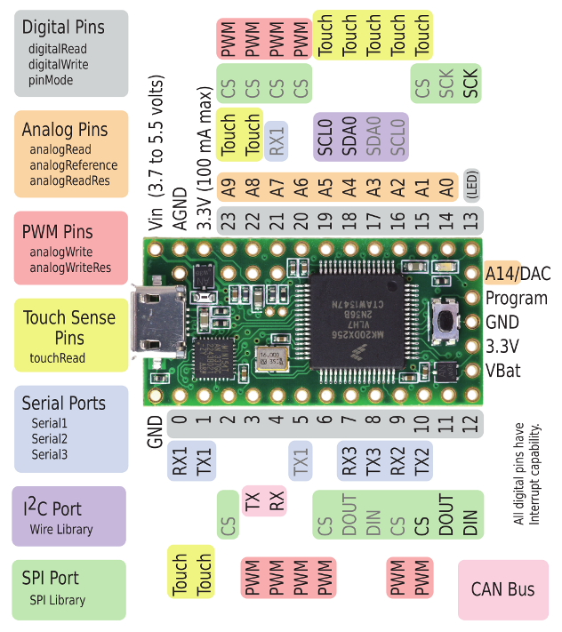
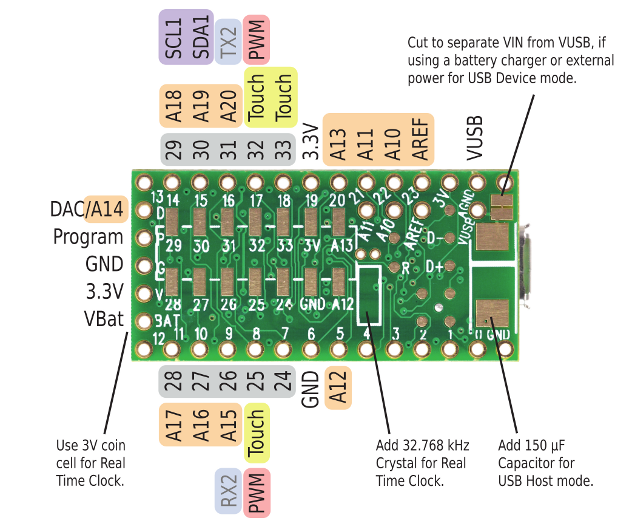
I can't help you re: how bit-banging code that was written for AVR works so well on a Teensy, but I'll wager an ice cream that you will see some sort of reference to all that in the AVR section of the Teensy3 core. Just as cli() and sei() are supported on the Teensy even though its internal references re: interrupts are different. (Paul supports this via #define statements in the pin files). All that said, the page you pulled up is for the Teensy 1, 2, 2++, and so on. The schematic for the Teensy 3 is attached below:
I can perhaps help you a bit more with the schematics. There were three types of references on the schematic associated with each pin.
One is the physical pin number on the 64-pin package. That's largely irrelevant to anyone except the folk who want to roll their own version of a Teensy.
The next pin reference like PTD4 describes the reference manual name associated with each physical external pin.
Some are easily accessible like the power-related pins (VUSB, VIN,VOUT3.3, VCC, VBAT, GND, AGND), there is the RTC set of pins, and finally communications pins like USB.
There are also difficult-to-access pins like the ones dedicated to programming the MK20 (like PTA3), the MCU crystal pins, and so on. One notable difference between the Teensy 3.0 and Teensy 3.1 series of board layouts is that the Reset Pin was re-designated to be A14/DAC on the 3.1. Thus, while Reset is easily accessible on a Teensy 3.0 board, it is difficult to access on a Teensy 3.1.
The remaining reference is one of several types that we can easily interface with the IDE, i.e.:
Analog I/O pins like A8, AREF, DAC (on the 3.1), and so on.
Digital I/O pins (and some do dual duty as digital or Analog pins) like D4.
Note that some of the multi-use pin designations are not listed on the schematic page (it only lists A0-A14). For a more complete set see:
and
Keep in mind, there are some additional analog inputs that are software-only accessible, like A38, which helps you determine the MCU temperature.
For bit-banging see the file ...\hardware\teensy\cores\teensy3\core_pins.h in your Arduino 1.0.6 distribution directory (once it has been overlaid with the Teesyduino files). On line 352 or thereabouts is the pin mapping which starts with this line:
Code:
#define CORE_PIN0_CONFIG PORTB_PCR16
It shows that Teensy pin 0 is internally pin 16 on PORTB.
I've attached an Excel spreadsheet I made of them with some added info.
As you can see in avr_emulation.h, it's "calling" digitalWriteFast() and digitalReadFast(). This stuff is all inline, so your AVR bitbang code is automatically translated to the equivalent Kinetis K20 bitbang code.
You could hard-code Kinetis registers, but there's no performance advantage, and it results less readable and more difficult to maintain code. Using digitalWriteFast() and digitalReadFast() with constants always results in the most optimal inline code.
But if you want to hard-code registers into your program anyway, go ahead. There's already a good number of threads on this forum with the details. The actual registers are documented in the reference manual. The real one difference from AVR is registers to configure the ports. Once configured as GPIO, they work pretty similarly.