Multiple (8) DAC outputs - how fast?

Status
Not open for further replies.

dslocum

Well-known member
I'm VERY new to the Teensy.

Thinking about the Teensy 2.0 ++. Just found out about it today. Looks really cool. (BTW - hate the newbie term but if that's what I am, so be it)

Anyway - I'd like to update eight 12 bit analog outputs at a rate of about 40 Hz with various software table lookups per output. I'd also need background time for up to 4 A/D reads, a couple bit inputs and at least one interrupt.

I'd love some comments & suggestions on how I might do this - and if it's even possible.

Will this CPU handle this in C? Are the (filtered) PWM outputs up to the task? Should I use external DACs ? Could they handle the SPI throughput?

Has anyone been down a similar road? Feel free to ask questions.
 
Here's a page with info about PWM details.

http://www.pjrc.com/teensy/td_pulse.html

If you use analogWriteResolution(12) and analogWriteFrequency(11718), you'll get exactly 12 bit PWM resolution when Teensy 3.1 runs at 48 or 96 MHz.

40 Hz is pretty slow. Unless you're doing something with tremendous overhead, updating 8 PWM pins at 40 Hz should be pretty simple.

With a 11.718 kHz PWM carrier, you should be able to make a pretty reasonable filter (8 of them) and still get 40 Hz bandwidth out. Of course, the usual caveats of using PWM for analog apply, such as changes in the power supply change your output voltage, so if you need really low noise or very high accuracy, a proper 8 channel DAC with very stable reference voltage might be a better choice.
 
Has anyone been down a similar road? Feel free to ask questions.

what are you trying to do?

using an external DAC is usually preferred over doing filtered PWM, especially if decent accuracy, slew rate etc are important.

i can recommend TI DAC8568, for instance, there's also a 12 bit version (DAC7568); i've been using it with teensy 3.x

either way, as Paul said, 40 Hz isn't very much.
 
Thanks for the good feedback guys!

However, the way I figure it is if I need to lookup and output say, a 12 bit sine wave using a LUT there would be 4096 output writes to complete one sine cycle.

Multiply that times 8 channels at a max frequency of about 40 Hz, I get somewhere in the area of 760 nS per output. 4096 / 8 / (1 / 40Hz).

Absolute accuracy is not important. This will be used in music synthesizers LFO.

760 Ns is pretty fast and I'm thinking that even if it were possible, there would be precious little time to do anything else. Will the DACs (or PWM outputs) even communicate that fast?
 
A 12-bit sine wave doesn't mean that you need 2^12 = 4096 samples to generate it -- it means that each sample is 12 bit accurate. The oversampling ratio (i.e. the number of times you need to sample -- i.e. generate a new PWM value) actually depends on the (analog) filter you are using between the PWM and the output you are using. Roughly speaking, if you use (say) 10 samples per cycle (e.g. update the PWM at 400 Hz to generate a 40 Hz output), you would need a filter that filters out signals at 400 Hz and above (the unwanted component of the PWM), yet allows 40 Hz and below through.

So you only need to update relatively slowly compared to your calculation above.
 
Agreeing with the others who suggest using a real multichannel DAC rather than messing around with filtered PWM. PWM needs to be filtered, so you still need external components (avoiding these often seems to be a reason for going for PWM rather than a DAC).

And yes, for 12bit output, 4096 is the number of voltage levels. This is unrelated to the number of times you update those voltages. For a 40Hz LFO your minimum update frequency would be 80Hz and each update would need 2 bytes times 8 channels = 16bytes = 128bits. Times 80 is 10240 bis per second, which is pretty slow; easily within the capabilities of an SPI DAC.

As an example, I am making an 8 output 16bit DAC which generates 5V CV for a modular synth. The circuit is just the DAC8568 octal 16bit DAC, two TL074 op-amps, 8 resistors and a few decoupling caps. You are welcome to take a look, if seeing an example would help:
https://github.com/Nantonos/ondesModulaire/tree/gh-pages/wavemix controller
In that example, the DAC and buffer op-amps are on one small board while the Teensy, connections for switches and sliders, an I2C expander to control 8 bicolor LEDs, and a logic voltage translator (from 3V3 to 5V) are on a separate board.

However, for your LFO application, it would be easier to skip the logic level converter: use the 3V3 version of that DAC (which has a 0 to 2.5V swing) and then do the shifting and gain in the op-amps to give +/- 5V swing which most synths will need for an LFO. (4x gain, offset to center the waveform on 0V and avoid the need for a DC blocking cap on the output).
 
ah, ok. updating something "at a rate of about 40 Hz" isn't the same as generating a 40 Hz waveform, but as the others have mentioned, it'll still be ok.

fyi/fwiw, the DAC8568 seems to do ok with 3v3 logic when run from 5v (0.625*AVdd), or what is the logic converter for?
 
What does "12 bit sine wave" actually mean?

There are a lot of meaningful ways to talk about sine waves. Often distortion is the main requirement, expressed as percentage THD. Often the accuracy of the frequency matter. Sometimes stability (change in the frequency over time) matters. Sometimes accuracy and/or stability of the amplitude matters.

My point is saying "12 bit sine wave", with very narrowly focused questions (based on incorrect technical assumptions) and giving very little info about the actual goals of your project pretty much guarantees you'll get less useful help, while also taking up more of everyone's time.

Just to further make this point, if you impose an arbitrary requirement that the sample rate is 4096 times the sine wave frequency, you end up with a rather silly notion that a 164 kHz sample rate is required! I'm pretty sure everyone can agree CD players are considered "16 bit audio" (4 more bits than a "12 bit sine wave") and very capable of reproducing excellent quality output for low frequency signals, even though they operate with much lower than 164 kHz sample rate. Clearly 4096X sample rate isn't necessary.

What is necessary, to really use a forum like this, is explaining what you're really trying to accomplish. Then we can talk about things that would really help you to achieve your goals.
 
the DAC8568 seems to do ok with 3v3 logic when run from 5v (0.625*AVdd), or what is the logic converter for?

DAC8568 is available in 4 grades. A and B have a full scale range of 2.5V (and a drift of 25ppm/°C); C and D have a full scale of 5.0V (and a drift of 5ppm/°C) but require 5V power. Grades A and C reset to zero (good for unipolar CV signals) while grades B and D reset to midscale (good if generating an LFO with no DC blocking, and a static midscale offset).

Since I wanted 0 to 5V out I picked a grade C; at first hoping to just run directly with 3V3 logic, then on reading the datasheet further I thougt it might be safer to use a translator as 0.625 × 5 = 3.125V seemed a bit too high a logic transition level for a 3V3 system. I wasn't sure if the minimum value for logic high from Teensy 3.x (given in the K20 datasheet, table 5.2.3 as Vdd - 0.5V = 2.7V) would be reliable. Useful to know I could have missed that SN74HCT125N translator out (but the PCB with it included is being fabbed now, so might as well use it).
 
Last edited:
Thanks again one and all.

Nantonos - thanks for that link- good stuff. Sound like our designs have some things in common!

Yes, I should have elaborated on my design. Let me try to clarify and address your points...

This will be an "arbitrary" waveform LFO under CPU control. There will be several pre programmed waveforms for each output. Waveforms might include sine, random fluctuations, sawtooth, etc, and may have different waveforms and/or different phases at any point in time. The desired MAX rate for each of the LFO outputs is around 40 Hz, with a minimum rate on the order of 1 cycle every 60 seconds.

Absolute accuracy is not important, but relatively smooth steps with 12 bit resolution is important as to cause minimal audible aliasing at steep slopes. I'll have a simple 2 pole output filter to help smooth aliasing steps.

Hope this sheds a bit more light on my goals.
 
Nanotos,

I am curious why you chose to put multiple op-amps between the DAC and your CV outputs, and not use a DAC8568C which is capable of outputting 5v right off the chip, and installing a single op before the DAC8568 providing 5v as reference and input to the DAC?


I ask this because I am also implementing an 8x CV solution for a project I am working on. I am using an Analog Devices AD5669 (i2c, but otherwise very similar to the 8568).

I have a breadboarded circuit working that takes both the Vdd and Vref from the Teensy Vin (USB power) giving me 5v.
I think this is a bad idea, but I dont know why. Is USB power reliably 5v? My final project will either be getting power from a USB source, or from a eurorack 5v power line.
 
I think this is a bad idea, but I dont know why. Is USB power reliably 5v?

probably a bad idea. though it somewhat depends on what is meant by usb power (coming from a notebook ? or some wallwart/psu which happens to use a usb connector?)

in this case, at any rate, you want a as-clean-as-possible power supply and reference. if you have a 5v rail, why not use it.

as for op amps etc, see here for a fairly extensive discussion of that family of DACs + teensy / eurorack.

https://forum.pjrc.com/threads/26974-Interfacing-with-TI-DAC856x-DAC816x-or-DAC756x
 
Is USB power reliably 5v?

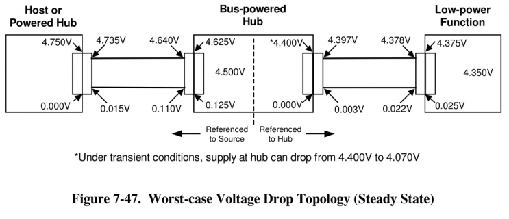
No, USB power can span quite a large voltage range.

This diagram from section 7.2.2 of the USB 2.0 spec really sums up the bad news.

voltage.png

It can be as low as 4.35 volts average, and even down to 4.07 volts for brief transients.

While section 7.2.2 says the maximum is 5.25 volts, some USB hubs are designed with 5V power supplies that push slightly higher when only lightly loaded, and probably don't hold up the required 4.75V minimum under worst case loading. There's tremendous price pressure on USB hubs, so this is one way they can cut costs.

If you're designing a one-off project, and especially if it will always be used with a high quality computer like a Macintosh, you can probably depend on the USB power being pretty consistent.

If you're making something that'll be plugged into lots of different systems, plan on the USB power varying from 5.5 to 4.0 volts. Usually it'll be pretty close to 5 volts, but no always, and especially not when plugged into an unpowered hub.
 
Status
Not open for further replies.
Back
Top