Appallingly small RTC

Status
Not open for further replies.

onehorse

Well-known member
I am in the middle of designing and building an accurate I2C RTC add-on board for the Teensy 3.x and finally have something interesting to show.

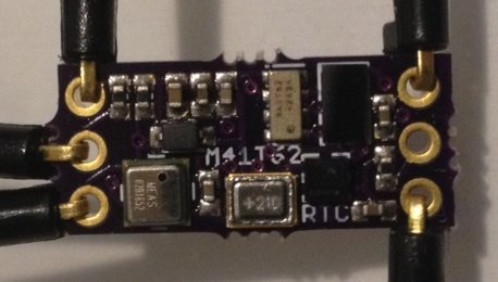
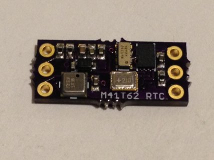
The hardware building blocks are the M41T62LC6F RTC with embedded crystal and oscillator that is super small, a M24512DFC 64 kbyte EEPROM, an MS5637 pressure/temperature sensor, and a Taiyo Yuden PAS3225 14 mF super cap and 1N4148 diode to keep power on the timer when separated from power or when the battery conks out or has to be changed. These have been integrated onto an appallingly small board intended to mount directly onto the Teensy 3.x and use 3V3 and GND from digitalWrite(HIGH) and digitalWrite(LOW), respectively, in this case from pins 15 (3V3) and 10 (GND), while using the I2C port at 16/17. The interrupt signal out is on pin 9 and the programmable square-wave output is on pin 8. Here is a picture of the first board and how I hooked it up using jumpers (notice I am using digitalWrite to pins 10 and 15 to power it!):
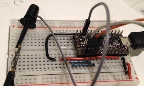
M41T62.pic2.jpg M41T62.pic1.jpeg

I don't seem to be able to upload any pictures with the usual uploader, but the basic one works!

Well, my plan is to work on the software while I'm at CES to use the (512 Hz) square-wave output as a reference to measure the output frequency and use the error (deviation from 512.000 Hz) to correct the clock periodically (every 10, 100, or 1000 seconds TBD) using the internal calibration register of the M41T62. The pressure/temperature sensor is there to measure the clock error as a function of temperature, but in the end I expect that the calibration function will just keep the clock in tune no matter what the condition. To be demonstrated.

This is an intermediate version; the latest has an ST HTS221 humidity sensor squeezed onto the board so it can serve as a remote weather logger (finally have a use for the EEPROM!; it can also store the measured RTC calibration vs. temperature curve).

In addition to testing the calibration routine and seeing whether I can approach and then surpass the quoted +/- 2 ppm accuracy of the M41T62, I would like to test how long the supercap can keep the timer going without power. The specs say the cap can supply 5 microAH and the timer needs ~330 nAH at 2.6 V, so I expect to get at least 15 hours out of the super cap. But I will likely get more since the timer keeps running down to 1 V. Can this setup go 24 hours without power and still keep proper time? If so, that might be very useful.

This is close to how I envision this board will be used:
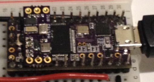
M41T62.pic3.jpg

It's not here but in actual use it would just be soldered to the Teensy 3.x and keep accurate time without the external 32 kHz crystal or battery required by the native RTC embedded in the Teensy 3.x.

This was a fun board to design but tricky to assemble since I placed the caps so close. In my first attempt some of the caps slid around a bit and got just a tad askew. Well, pretty will be for later versions that I will no doubt try to sell at Tindie.com.
 
Last edited:
That is so awesome! :p

Congrats and I hope it works as expected!!! With an external Lipo + solar charger, this would make a kicking (and tiny!) weather station / data logger.

PS: I wonder if you will find some sort of correlation between the supercap voltage and clock drift.
 
Impressive!

Please report back when you've done tests on how long the supercap lasts, I'm very interested in that.
 
I wonder if you will find some sort of correlation between the supercap voltage and clock drift.

Please report back when you've done tests on how long the supercap lasts,

My first test was packing up the board for the road trip to CES. The board was unpowered at exactly (near about) 11:00 PM and re-powered at 11:33 PM the next day (tonight). To my surprise and dismay the clock reported the correct day, date, and year, but was 1 hour and 24 minutes slow compared to ULT (universal laptop time). This means that sometime during the 24.5 hours unpowered the supercap voltage fell enough to produce unreliable timing of the RTC but not enough to cause it to return to its completely ab initio state. It was slow not dead.

Next on the docket is a 12 hour test. I will see if I can narrow down how long it takes before the time keeping is seriously affected.

Update: The 12 hour and 8 minute test worked perfectly; the time was in agreement with ULT as it had been twelve hours before with no power supplied during that time. I'll keep trying to hone the time threshold for the onset of error. Now somewhere between 12 and 24 hours. The super cap is already meeting my expectations.

Update: I ran tests at 16 hours and seven minutes and at 18 hours zero minutes and both produced the correct readings to within one second as far as I can tell. So the accuracy threshold is now somewhere between 18 and 24.5 hours for this PAS3225 super cap running the M41T62 RTC timer. I'm very happy with this performance so far since it means even lost power for most of a day won't result in lost time registration. The super cap is a very convenient back up power source.

Update: I ran a 21 hour and 20 minute test and the clock was one hour and 47 minutes slow. So the power capability of the PAS 3225 is somewhere between 18 hours and 21 hours. This is better than I expected. I would still like a more or less accurate failure threshold so I will perfrom one more test at 20 hours if I can.

Last update on the super cap: I ran a test at 19 hourse 21 minutes and the clock was seven minutes slow. So I am going to call the threshold for errorless run time of the M41T62 RTC using the 2.6 V PAS3225 supercap at 18 hours. I think the voltage drops very rapidly once the supercap reaches its 5 microAmpHour limit. More detailed testing is in order, but for now its an 18 hour batteryless backup. Not too bad!

On another note, I tried to use freqMeasure and freqCount but realized after ten seconds of actually reading about these functions that they only allow use of specific (and far away) pins on the Teensy 3.1. I wonder if there is some way to measure frequency of a square wave on any old GPIO pin (like pin 8)? Couldn't I just count rising or falling edges for a "fixed" time interval to approximate a frequency measure? Yes, I know, the fixed interval isn't. Any ideas from those who know?

I will attempt to use a simple timer function to count edges to see if this works for a poor man's frequency counter on GPIO pin 8. Will report progress (or lack thereof)...

I finally succeeded in measuring the frequency of a square wave output on pin 8. I will post the function and more results tonight...
 
Last edited:
Update on my doings with the M41T62 RTC:

The version of the M41T62 I am using is the smallest package in the ST RTC lineup but it is the only one with an embedded matching oscillator and crystal so no external crystal or passives are required. Sweet!

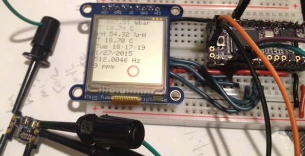
I managed to assemble the final design with the added HTS221 humidity sensor and everything is so far working well. Here is what the latest version looks like:

M41T62_HTS221.1.jpg

There are two changes; I added the ST Microelectronics HTS221 humidity sensor, which at 2 mm x 2 mm I just barely had room to squeeze in, and I replaced the 64 kByte M24512DRM EEPROM with a 256 kByte M24M02 EEPROM. I took a little more care with the soldering also so the board is a little prettier, but the silkscreen is mottled because of all the vias I had to use.

I am using the latest Sharp LCD display on an Adafruit breakout to access all the data, which only requires three wires + 3V3 and GND for a 96 x 96 pixel display. These are pretty nifty being thin, only 3 g and requiring less that 40 uAmp to run.

M41T62_HTS221.2.jpg M41T62_HTS221.4.jpg

In fact the entire board is a wonder of small size, low power, and sophisticated capability. The total power budget for the two sensors, RTC, and EEPROM is less than 135 microAmps at a 1 Hz data rate. In principle a 40 mAH battery should power the board for a week but in fact it didn't last twelve hours. That's because the Teensy takes a fair amount of power. I would like to run the Teensy at 2 MHz or 8 MHz but all the devices communicate via I2C and the FBus cannot go that low. At least I don't know how to make I2C (i2c_t3.h) work below 24 MHz clock speed on Teensy 3.1.

I already reported that the Taiyo Yuden PAS3225 14 mF supercap keeps the M41T62 RTC timer going for at least 18 hours. But I'd like to get the entire device to operate remotely on a small LiPo battery for several days or longer. Power reduction is the last unsolved problem with this project.

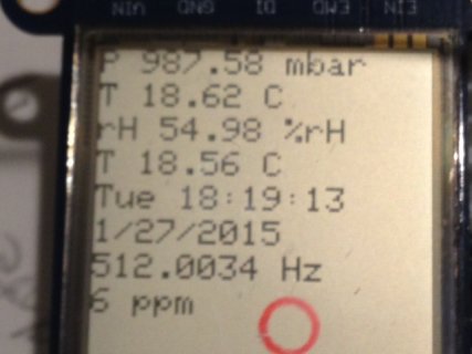
I was having trouble using the FreqMeasure library since I planned to use pin 8 (or at least a pin close to the I2C ports) and FreqMeasure requires the use of only certain pins. That's OK though, because with the help of this short but excellent example I was able to get a pretty good frequency measurement of the programmable square wave output to pin 8 from the RTC. You can see in the picture above that the measured frequency is very close to the 512 Hz programmed into the RTC. I tried frequencies from 256 Hz to the full 32768 Hz but the error shown as parts per million didn't really depend on the frequency so much as the integration time. I started at 100 ms as in the example I so shamelessly copied from but ended up at 800 ms which at the ~20 degrees C temperature shown produces a frequency error of 9 +/- 1 ppm. This is exactly what I was hoping for. The RTC can be calibrated through a register write where each of +/-31 bits (0x1F plus a sign bit) represents either 4 ppm faster (positive value) or 2 ppm slower on the clock train.

The way I have the code set up now, I am updating the calibration register every second (probably overkill). This has the advantage that no matter what the temperature or other condition that might affect the clock speed, it is automatically compensated for by this procedure. The +/- 1 ppm jitter comes from the finite integration time and other errors inherent in the timing source (the Teensy). But it should be possible to achieve at least the 2 ppm accuracy limit claimed by the data sheet using this method.

The next step is for me to log data using the EEPROM. There are 16 bytes of useful data generated by all the sensors and clock. At a 1 Hz write rate that is more than four hours of data. But these sensors don't change their value very fast. So a more sensible once-per-minute logging would record pressure, temperature and humidity data with an accurate time and date stamp for at least ten days with 256 kBytes of non-volatile EEPROM. If I can squeek out ten days on a single battery charge, this board plus a Teensy 3.1 (or maybe even a Teensy lite) would make a very compact and useful environmental data logger.

The last characterization task is to vary the temperature and map out how the clock speed (or frequency error) varies with temperature. ST publishes a canonical quadratic curve for their RTC but each crystal is different and should be characterized individually. This set up with the on-board temperature sensors and automagical frequency measurement will make this characterization task easier. I'll update when I get something...
 
Last edited:
Really enjoying this thread!

For data that changes so slowly, run length encoding or some other form of compression might work well.
 
Appreciate the feedback. What is run length encoding?

I was planning on storing the raw data bytes since all of the scaling, etc to reconstruct the meaningful data can be done off line.

BTW, I used a power supply to confirm that the Teensy 3.1 + RTC board + display is consuming 20 mA so it is no surprise my batteries are conking out after only a few hours. This weekend I will try out Duff's Snooze library to see if I can cut this down to ~2 mA. I plan to put the Teensy to sleep and wake it up every ten or twenty seconds to measure all the data, output to the EEPROM and display, update the RTC calibration register, then go back to sleep. I will use the RTC alarm and RTC interrupt as a wake signal. I am hoping I can adjust the duty cycle to get the power down significantly and balance the power versus data rate for ten day operating period.

I am even toying with the idea of adding an nRF24L01+ 2.4 GHz radio so I can get updates remotely. This is such fun!
 
Run-length encoding is a very simple compression technique for data that contains lots of consecutive repeats. The idea is to store a repeat count and the value to repeat. So for example, if your data is: a a a a a a a a a b b b, you'd store it as 9 a 3 b. This takes 12 symbols down to 4 in this example. As with all compression algorithms, there are inputs that 'compress' to something larger, so it pays to know your data.

Another trick is to run-length encode the deltas. This might be useful if the values were large but only changed slightly, like perhaps timestamps.
 
One trick I have used before is to store the time as simply the number of minutes since start. This could save several bytes of storage.

But I think 16 full data bytes is already pretty compact and, since I only want ten days for now, I might forgo any fancy compression techniques. Besides, I am too lazy to parse individual bytes. I suspect I will be limited by battery life anyway, not data storage capacity.

And even if i can somehow get the power to last for a month (by using solar cells for trickle charging! as suggested by Constantin) I would rather just add another 256 kByte EEPROM (one more can easily be added since they have a one-bit address toggle) than fuss with compression.

But for serious longevity I can see the value, and clever people would probably be able to make better use of the data capacity, as you suggest...
 
In my event driven logger, I set thresholds for when something is considered interesting (i.e. more than 5W deviation from the min or max) before the unit starts logging in high speed mode.

Otherwise, it simply averages a whole series of data points into two entries, i.e. 'an average of x over a y period' while keeping careful track of accumulated Wh, and so on.
 
This is a good point and one I hadn't considered but i could keep track of average pressure and humidity and only log data into the EEPROM when a significant change is detected. I'll get the basic an simple capability working first before I try getting too fancy though...
 
I did a simple test with Brian's new i2c_t3.h library v.7 and was able to run this environmental sensor at 2 MHz. This is a great capability. Unfortunately, 2 MHz is too close to the polling frequency of the square wave (?) such that I was getting significant error in the value ~506 Hz instead of 512 Hz. Not quite sure what the problem is but going to 4 MHz cures it. The LCD screen update is noticably slower but all the values look good and the square wave reports 512.0046 Hz as usual. This reduction in clock speed saves me 9 mA (from 20 mA at 24 MHz to 10 - 11 mA at 4 MHz), which is already a big win. Now to see how much more I can save using Duff's snooze treatment.
 
Is this RTC going to be up on your Tindie soon, or is it a way off yet? (Asking so I know whether to order some of your other stuff now, or wait and get the RTC as well).
 
data logging - like GPS reporting....
Report (log) by exception, in GPS
distance moved > x
Heading change > x
If immobile, time since last report > x1
if moving, time since last report > x2
and so on.

report by exception, not a fixed time interval.
 
Spot on, Steve, but how often do I see data loggers that only log at fixed time intervals and hence record a lot of non usable data. It's really frustrating.
 
Is this RTC going to be up on your Tindie soon, or is it a way off yet? (Asking so I know whether to order some of your other stuff now, or wait and get the RTC as well).

I will put them on Tindie this weekend. I was waiting 1) to get a little further along reducing power consumption, 2) getting some experience logging data, and 3) getting a source for the humidity sensors. I will list both the RTC with and without humidity sensor for sale since not everyone wants to know how moist it is!

data loggers that only log at fixed time interval

Well, pressure and temperature do undergo the usual diurnal quasi-sinusoidal cycle. I admit one-minute intervals is likely too frequent but my plan was to start with regular intervals, get a better idea of what the data really looks like, and then adjust to extract the most information with the least fuss. So in the end I might just end up logging "significant" changes, but in the beginning I want to know everything, even if it is boring and repetitive.

BTW, I ordered a flexible 100 mA 4 V solar cell that is, IIRC, 2 in x 3 in that I want to try to use to charge the LiPo battery. I also am intrigued by the 4 V, 100 uA, 6 mm x 10 mm solar "chips" I found on Mouser. I could design a shield to fit 4 or 5 of these chips within the Teensy form factor and still have room for the RTC/environmental sensor board and the LiPo charger. If I can manage the power just so, I might get many weeks of remote operation with these solar cell chips and maintain the appallingly small package I strive for.
 
Last edited:
Spot on, Steve, but how often do I see data loggers that only log at fixed time intervals and hence record a lot of non usable data. It's really frustrating.
Yes. I've done big vehicle fleet management projects for commercial and military. They ALWAYS put in the contractually obligatory specs "send location every x seconds". Once, I did a study of historical data (huge volumes of reports) that showed irrefutably that 90% of the reports were redundant. In commerical, that costs $$$ of air time. In military, it causes wireless congestion.
I wrote a paper on what makes sense, i.e., report by exception. Presented it far and wide.
Next procurements - same crap.

for an autonomous data logger with its own mass storage, not so much of an issue. Except for the post-mission data reduction software!

Totally agree, but the problem of data white-out is more general.

Recording high quality raw data without preprocessing makes only sense if the data collection is expensive. Say, if you collect data from a ship in the ocean that cost about 1 MioUSD/month, you store all what you can and bring it home, even if you do not have the time and processing facility to digest all the data.

All cases, where one is looking for anomalies (i.e wanted to detect some signal/events in noise) then it make only sense to record the event/signal and not all data, which are mostly noise.
That is also, why modern accelerometers, while giving orientation, can give you an alarm (e.g. zero g => falling).

In this sense, anomaly detection, if well defined, is best done in hardware, then, if possible, at the sensor location (teensies are good for that) and only if you don't know what you are looking for, at the users end.

The only problem with event driven software is the marketing, i.e. convincing the customer, that the probability of miss AND the probability of false alarms are both low. while accepting errors from humans they seems to be unacceptable from machines.

Also, it seems to be not easy to classify/describe positively events. Even classical signal processing describes signal as non-noise.
 
My motivation re: event driven reporting has everything to do with making the data sets manageable. The logger is operating on a second by second basis, and though the SD cards are unlikely to ever run out of memory, the accumulated data files would amount to 2.6MM lines per month. I'm motivated in part to keep the data in a format that is compact enough to allow my colleagues to run the analysis in Excel rather than SAS, R, etc. because they're familiar with the former, not so familiar with the latter.

Additionally, most appliances sit in standby mode most of the time. Accumulating junk data can take your eye off the events that are interesting. By setting thresholds or other flags that trigger second-by-second recording, you get a consistent recording of 'interesting' events while compressing the 90% that have relatively little to contribute. One of my main challenges (because this is the first time I'm programming this) is how to take on a network of sensors and do event-driven logging for them. That's a subject for a separate topic, however.
 
I think in every specific new application fixed time interval logging is required before an event-driven logging scheme can be designed. If you don't know what your looking for, how will you know how to tell the microcontroller how to find it?
 
Spot on.

That said, you can give your users a number of thresholds to choose amongst from the very outset. In my application, those thresholds can be watts, temperature, humidity, light, etc. related, each with its own scale.

For me, the bigger challenge is how to coordinate low speed (i.e. averaging) mode vs high speed mode among the 250 potential devices on the bus. I think I'll resort to polling from the master to the slaves, tallying how many high speed flags that returns, followed by telling the bus to keep averaging or to dump the previous average and start logging second by second.
 
Status
Not open for further replies.
Back
Top