
You are using an out of date browser. It may not display this or other websites correctly.
You should upgrade or use an alternative browser.
You should upgrade or use an alternative browser.
Teensy 3.1 and FastLED 3.0.3 Compatibility
- Thread starter jaxter184
- Start date
- Status
- Not open for further replies.
PaulStoffregen
Well-known member
I highly recommend using some sort of magnifier, like a jeweler's loope, and a very bright light, so you can see the pads and trace in good detail. Once you can see it well, things should become very clear.
An Exacto knife works well for making the cut.
If you later decide to reconnect VUSB to VIN, it's pretty easy to use a soldering iron to bridge those pads back together with a bead of solder.
It might also be worth mentioning that you do NOT need to make this trace cut if you're using USB. It's perfectly fine to have the LEDs powered from their own power supply, and the Teensy powered from the USB cable. In that setup, only the grounds of the 2 power systems connect together.
Generally, you would want to cut the trace and run Teensy from VIN when Teensy is NOT using the USB. Projects where Teensy does all the animation or LED control, without a computer connected by USB, are the projects where Teensy needs to get power from the local system.
In that case, I probably shouldn't cut the pads.
The adafruit website says to use a 1k uF capacitor and a 330 ohm resistor, so that is what I am using. It works on other microcontrollers, so I don't believe that is the issue.
The capacitor right after the power supply is labelled "1K uF", is it really 1 Farad? If so you might want to try some different values with that to see if it's a noise problem, e.g. in parallel with that add one or a couple of 0.1 uFs, 4.7 uF, etc.
The adafruit website says to use a 1k uF capacitor and a 330 ohm resistor, so that is what I am using. It works on other microcontrollers, so I don't believe that is the issue.
potatotron
Well-known member
The adafruit website says to use a 1k uF capacitor and a 330 ohm resistor, so that is what I am using. It works on other microcontrollers, so I don't believe that is the issue.
Sorry for the confusion. I didn't mean replace the 1 Farad cap, I meant try different values in addition. It's possible it's a problem with noise from your power supply and using different capacitor values should reduce that. A 1 Farad cap will only eliminate very very low frequency noise, and it's primarily there to help with the inrush of current needed going from all off to all on full brightness etc.
This is a longish video that explains what I'm talking about:
https://www.youtube.com/watch?v=qb1QFh_fxDo
Skip to about the 4:00 minute mark to see an example.
[edit - typo]
Last edited:
Awesome blog post:
Testing level shifters for running Adafruit NeoPixel strips from a 3.3 Volt Teensy
By Jez on February 9, 2014
http://happyinmotion.com/?p=1247
Testing level shifters for running Adafruit NeoPixel strips from a 3.3 Volt Teensy
By Jez on February 9, 2014
http://happyinmotion.com/?p=1247
Coincidentally, my teensy came in earlier and I just hadn't noticed. It seems that the problem persists, so it's not an issue with the teensy.
EDIT: Also, I tried cutting the pad, and that only broke things more. When it's cut my arduino/teensy hybrid workaround doesn't work.
EDIT: Also, I tried cutting the pad, and that only broke things more. When it's cut my arduino/teensy hybrid workaround doesn't work.
Last edited:
https://www.youtube.com/watch?v=dn7kxIdFNso
A video of me troubleshooting with explanatory annotations.
A video of me troubleshooting with explanatory annotations.
I was thinking, is it possible that the data pin sends signal at a higher voltage if the ground is connected to an arduino? That would explain my issue.
In addition, is it possible to get a voltage converter with fewer pins? The one that Chris O and nlecaude suggested would be fine for the final product, but for testing, I would prefer to have something a little simpler just so I don't mess anything up. Also, what would prevent me from just getting a voltage regulator for this purpose?
Link to the logic shifter for reference: http://www.digikey.com/product-detail/en/74HC125PW,118/568-7623-1-ND/2753767
Also, what is the purpose of the 100 ohm resistors on the OctoWS2811?
Last edited:
Sorry for threadjacking but if you're just looking to level shift a single GPIO pin and only one direction, couldn't you just use a simple transistor?
I only just noticed this. Can you just get transistors on their own? I had no idea.
Also, I tried the all three semiconductor things and only one worked, and even then, it worked really strangely. I'm still confused as to what is going on. I will post a video asap.
Last edited:
pictographer
Well-known member
Hard to tell from the video, but it looks like some of the electrical connections you're making might not be reliable. To get a good connection, you need either some sort of constant spring force or solder.
PaulStoffregen
Well-known member
I'm about to package up 1.12-beta6. Should I update FastLED? Can anyone recommend which version/branch would be the best to include at this point?
Teensy 3.1 + WIZ820io + LPD8806; which FastLED? SPI transactions support?
I too am wondering:
1) What is the latest and greatest FastLED for use on Teensy 3.1?
2) Does/will FastLED support the new SPI API supporting transactions [now | anytime soon | ever]?
For context, my project involves using Teensy 3.1 + WIZ820io + PJRC Adaptor to drive LPD8806 based RGB LED strips using hardware SPI. I'd like to use FastLED because of the extra features (HSV support, master brightness setting, dithering) but it is not clear to me if both the Ethernet library and the FastLED 3.0.3 (latest) library can use the same SPI w/o SPI transactions. The Ethernet library in Teensyduino 1.20 has been updated to use SPI Transactions but I think FastLED has not.
I'm about to package up 1.12-beta6. Should I update FastLED? Can anyone recommend which version/branch would be the best to include at this point?
I too am wondering:
1) What is the latest and greatest FastLED for use on Teensy 3.1?
2) Does/will FastLED support the new SPI API supporting transactions [now | anytime soon | ever]?
For context, my project involves using Teensy 3.1 + WIZ820io + PJRC Adaptor to drive LPD8806 based RGB LED strips using hardware SPI. I'd like to use FastLED because of the extra features (HSV support, master brightness setting, dithering) but it is not clear to me if both the Ethernet library and the FastLED 3.0.3 (latest) library can use the same SPI w/o SPI transactions. The Ethernet library in Teensyduino 1.20 has been updated to use SPI Transactions but I think FastLED has not.
Last edited:
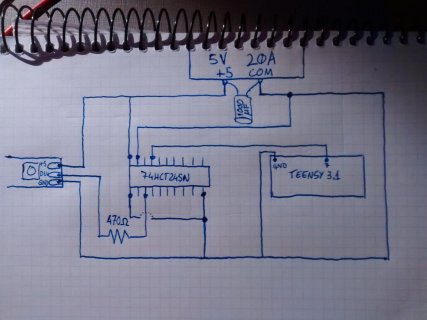
I ordered both a 74HCT245 and a 74HCT125, and neither of them are working correctly, on both the Arduino Uno and the Teensy 3.1s. Am I wiring them correctly? I have attached a picture of my circuit for the 245. I apologize for my crude drawing skills.

Datasheet for 74HCT245
Also, I've been thinking, since this thread is titled incorrectly, should I start a new one and leave a link in the first post of the new thread leading to this thread?
Datasheet for 74HCT245
Also, I've been thinking, since this thread is titled incorrectly, should I start a new one and leave a link in the first post of the new thread leading to this thread?
PaulStoffregen
Well-known member
The '245 chip has 2 control signals, for direction and enable. You have to connect both of those properly. Otherwise, it will not pass the signal.
GremlinWrangler
Well-known member
Ground for both could work, as long as you look at the data sheet and get the directions right since enable is active low but direction is active high. In this case direction low will have it activating the right hand side drivers so it will be operating in reverse (see chapter 5 fig 1) from your sketch. of note this may have damaged the Teensy so suggest a quick check with the blink sketch to that pin with an LED and make sure it can still drive. I've yet to destroy a Teensy3 that way but have a couple of AVRs with pins that are 'sad' from misadventures connecting two outputs to each other.
If this is on a breadboard I'd suggest wiring up an LED to the level converter output and confirming you can drive it by pulling the input high and low with a resistor (and check with a multimeter if you have one. Then connect up the Teensy and blink the LED, then load the code for the strip (but still flashing the LED) and then connect the strip. This breaks things down into known chunks if further trouble eventuates.
If this is on a breadboard I'd suggest wiring up an LED to the level converter output and confirming you can drive it by pulling the input high and low with a resistor (and check with a multimeter if you have one. Then connect up the Teensy and blink the LED, then load the code for the strip (but still flashing the LED) and then connect the strip. This breaks things down into known chunks if further trouble eventuates.
Thank you, I didn't notice that, I just assumed that the signal went from A to B. This part works fine now.In this case direction low will have it activating the right hand side drivers so it will be operating in reverse (see chapter 5 fig 1) from your sketch.
So I am now a little closer. The teensy works on its own. However, some of the messages seem to be a little off. I am running a script that changes the color from green to red and back repeatedly, but it only goes through one cycle each time I reset the teensy. The code I have is below. Thank you all so much for all of your help so far, I don't know where I would be without all of you.
Code:
#include "FastLED.h"
#define NUM_LEDS 91
#define DATA_PIN 10
CRGB leds[NUM_LEDS];

void setup ()
{
  FastLED.addLeds<WS2812B, DATA_PIN, GRB>(leds, NUM_LEDS);
}

void loop() {
  for (int each; each < NUM_LEDS; each++) {
    leds[each] = CRGB::Green;
  }
  FastLED.show();
  delay(1000);
  for (int each; each < NUM_LEDS; each++) {
    leds[each] = CRGB::Red;
  }
  FastLED.show();
  delay(1000);
}
Another code I tried results in all of the lights turning on successively, but not turning off as the next one turns on, which it should do. After all of the lights turn on except for the last one, the cycle restarts, but this time a single black dot goes through the whole strip. I'm still baffled. It's the opposite of what it should be doing. (The last light usually stays on due to my laziness in the code). Another strange thing that happens is that the first frame is a green dot in the first LED. Also, the animaion cannot be reset using the button on the teensy after the black dot starts moving through the strip.
Code:
#include "FastLED.h"
#define NUM_LEDS 91
#define DATA_PIN 10
CRGB leds[NUM_LEDS];

void setup ()
{
  FastLED.addLeds<WS2812B, DATA_PIN, GRB>(leds, NUM_LEDS);
}

void loop ()
{
  for (uint8_t k = 0; k < 91; k++) {
    leds[k] = CRGB::Black;
    leds[k - 1] = CRGB::White;
    FastLED.show();
    delay(500);
  }
}
The code works perfectly fine with Arduino, which, funnily enough, brings me back to the original topic. Is there anything I need to do in the code to make the teensy compatible with FastLED?
Last edited:
GremlinWrangler
Well-known member
For your first code try declaring 'each' as zero
for (int each=0; each < NUM_LEDS; each++) {
to define the value of each as 0 each time the for loop runs.
With the second one you need to swap the blacks and whites over. You are incrementing upwards through the array setting the current pixel to black and the prior one to white. Also be very careful of [k-1] type statements since for k==0 that will be writing to some random memory location
aka
http://en.wikipedia.org/wiki/Buffer_overflow
more complex programming systems will trap this sort of command, but Arduino will do exactly what it's told and happily overwrite everything. Always double check array pointers!
Alright, after a couple minutes of code fixing, I've fixed all pressing issues and can now begin refining my PCB design and order some of the more specific parts of my project. Once again, thank you all so much for following me on this arduous journey, and I apologize for my stubbornness. Literally the first suggestion I was offered worked perfectly, and I failed to use it until now. I may resurface later in the 'General Discussion' category, and maybe even offering help in this section as well, assuming my skills develop over time. You have all been a wonderful help to me, and my joy of having a working project cannot be described in words.
Once again, thank you.
Once again, thank you.
Pabloantxon
New member
Hi!
I´m sorry for bringing this thread up again, but I have been trying to get some WS2812B leds to work with a Teensy 3.1, and this was one of the only google searches I could find that helped me. One thing that I missed was a drawing showing the actual connections needed for the 74HCT245 to work. There is one, but as you say later it is incomplete.
So I wanted to upload the circuit that I made, in case someone arrives here with the same problem. The leds work great wiring things like this")

I´m sorry for bringing this thread up again, but I have been trying to get some WS2812B leds to work with a Teensy 3.1, and this was one of the only google searches I could find that helped me. One thing that I missed was a drawing showing the actual connections needed for the 74HCT245 to work. There is one, but as you say later it is incomplete.
So I wanted to upload the circuit that I made, in case someone arrives here with the same problem. The leds work great wiring things like this
Attachments
TimoLejeune
New member
Thanks a lot for this!
Hi!
I´m sorry for bringing this thread up again, but I have been trying to get some WS2812B leds to work with a Teensy 3.1, and this was one of the only google searches I could find that helped me. One thing that I missed was a drawing showing the actual connections needed for the 74HCT245 to work. There is one, but as you say later it is incomplete.
So I wanted to upload the circuit that I made, in case someone arrives here with the same problem. The leds work great wiring things like this
View attachment 6140
- Status
- Not open for further replies.