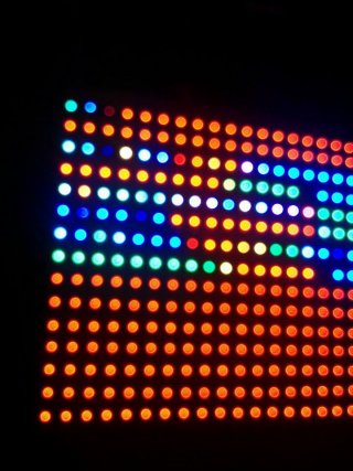
Panel led with audio animations

Status
Not open for further replies.

PaCOM

Member
Hi this is my first post because I recently decided to make a project with leds and I founf this amazing forum, since I am a newbie I hope you guys can help me and sorry if I make some dumb questions.

The thing is that I want to make a 2x2 ft (60x60 cm) panel led with audio animations, the thing is that I am about to buy 11 30/m 1m led strips and a 3.1 teensy with it's octows2811 adapter but I read that you have to cut something in the corner so you can supply the teensy with 5 V but I also read that the adaptor has a buffer chip so I am not sure if I need to cut the teensy or it is not necessary, another question, I have a 5V 10 amp power supply to power the 11 strips and I am not sure if I need another 5V 10amp supply; if I am going to use more than 8 strips do I need another teensy because I was wondering, the adapter has a jack with 2 slots for 2 CAT6 cables, 8 strips each cable, with 1 teensy i should be able to connect 16 strips right? Also another thing is once you solder the adapter to the teensy do you have an extra pin? I mean I need an audio adapter too but since you can't use the sd card with the ws2811 adapter I am going to connect a tip31 transistor or a microphone, either way I need a pin so the teensy recognize the sound and I am not really sure if I have one pin left. The last thing is that since I am trying to make this panel wireless and with wireless I mean that you don't need a PC connected all the time for the animations, Processing is my best option? Or is there anything easier besides FFT? Thanks a lot for everything.
 
Can answer some of your questions, can you please re-post your outstanding ones in a list rather than a chunk please.

The cutting the USB power track is is because you must have seperate 5V power for the LEDs, and the USB cable is also providing power. In the default configuration this normally means your high current 5V supply is driving into your PC and letting the magic smoke out. So you cut the track, the USB power does nothing on the board and the Teensy runs off your 5V power.

The Buffer chips are to provide the 5V drive signals to the strip from the 3.3V teensy output levels, and not related to the power.

With driving lots of LEDs see the description and warnings https://www.pjrc.com/teensy/td_libs_OctoWS2811.html By my math at max brightness you will need around 16 Amp which may not be handled well by your PSU. Suggest doing your testing with half the LEDS or upgrading your power arrangements. NEVER just say 'I'll never set them all to white' since it will happen during coding at least once.

With your strips to make a matrix, you can either run multiple teensys or daisy chain the strips, so the line one feeds row one L-R and row two R-L (or run a wire back the full width of the display) line two feeds 2 and 3 until you get to line 6 feeding just line 11 and lines 7&8 unused (or add strips) this will mean you are wasting memory and care will be needed not to display to the 5 unused spaces.

The twin RJ45 jacks are to use the twisted pairs in Cat5/6 cable for signal balancing so each cable handles 4 strips.

With the animations you have a range of options, but the good ones will require the FFT library and measuring frequency bins. Is possible to do envelope detection doing large numbers of samples and tracking max and min values then using that to feed basic intensity values to an existing noise or flow effect.

With the Audio input it's a case of utilizing one of the spare A/D pins as listed on the reference card, see other posts on the forum for achieving good sampling rates for audio.

Do see the various other LED matrix posts around the forum since there are a lot of ways to smoke money on this sort of project and strongly suggest building a mini version of say 8*8 pixels or maybe a single 30 LED strip and try some sample code to make sure things work. My suggestion would be to do an AV meter with a single strip and your audio input of choice. If the OCTO library isn't working with a single strip you can try the easier to use but much slower Adafruit neopixel library to confirm you have working hardware.

https://forum.pjrc.com/threads/27492-OctoWS2811-LED-Library-Help
https://forum.pjrc.com/threads/2375...our-160x80-Video-wall?highlight=matrix+WS2811
https://forum.pjrc.com/threads/26336-octo-basic-test-give-me-all-white?highlight=matrix+WS2811
https://forum.pjrc.com/threads/2686...-ws2812b-pixel-panels?highlight=matrix+WS2811
 
Thank you

Thank you for your attention and thank you for you taking time to answer me my doubts, I have a some other questions about your response tho, about:

http://www.pjrc.com/store/octo28_adaptor.html

That link that you sent me, I read it but I don't understand one thing, the image shows 4 strip connected to cable, it shows that the orange cable is connected to the first strip on the left.
The second strip is connected to the right, like continuing the first strip.
The third one is the same connection as the first to the second.
The 4 strip is connected the same way as the second and third, that means in that example the teensy will detect the first 4 strips like one right? that is why one teensy is controling the first 4 strips as one?
 
Paul thank you for taking time to answer me, but I have one question about that example, the thing is I don't fully understand the octo ws2811 adaptor, it is connected to the teensy using all the pins but the A14/DAC, the program, GND, 3.3V and the VBat pins.

My question is if I connect the adaptor to the teensy do I have more pins avaliable but these ones? in that example he uses the A3 pin and it is used by the octo adapter, the other thing that I don't understand about the adaptor is the adaptor have 14 pins unused, it has the 0, 1, 23, 22, 19, 18 and 17 numbers on the side, what are those for?

Thank you for your time and I am sorry about the beginner questions.
 
The 4 strip is connected the same way as the second and third, that means in that example the teensy will detect the first 4 strips like one right? that is why one teensy is controling the first 4 strips as one?

Yes, this is a normal configuration. Scroll down to the "VideoDisplay Example Program" section on the OctoWS2811 page. Look for the text that explains LED_LAYOUT, LED_WIDTH and LED_HEIGHT.

Without those settings, a video driven display would be limited to only 8 lines tall per Teensy. OctoWS2811 is designed to give you a lot more flexibility. But that flexibility does come at the cost complexity of understanding a number optional settings that let you configure for how your LED strips are arranged.

My question is if I connect the adaptor to the teensy do I have more pins avaliable but these ones?

Yes, of course. The OctoWS2811 software doesn't "know" whether you've soldered your Teensy to the Octo28 adaptor board, or simply connected resistors and wires. It always uses the same pins, as documented.

the other thing that I don't understand about the adaptor is the adaptor have 14 pins unused, it has the 0, 1, 23, 22, 19, 18 and 17 numbers on the side, what are those for?

Those pins on the side are meant to help you access the pins OctoWS2811 isn't using. Of course, you could also solder wires to the top of the Teensy after it's soldered onto the Octo28 adaptor. Or you could solder a stack of adaptor boards together with extremely long pins, as was done for this project. But sometimes those pads on the side might be more convenient. Or you can use a mix of any of these. Its your project and you have a lot of different options.

However, I highly recommend using the Octo28 adaptor, rather than wires and resistors as I did for the early OctoWS2811 prototype and example. Many people tried to build their project that way, some with success, but many others with frustration. The Octo28 adaptor and CAT6 cable has shown a much higher success rate among the many thousands of people who's built large LED projects with OctoWS2811 since it was first released in early 2013.
 
Panel.jpg

Thank you Paul for your time, I already built my panel and I was testing it with the basic test example from the octo library but It crashes, on the other hand I uploaded the fire example and it runs fine.

What do you think the problem would be? I got my teensy board solded to the octo adaptor and connected with CAT6 cables, 15 strips, 2 connected for each pin and the power supply is the board, I tried with a 5V 10A power supply but it crashes as well, what can I do?

Thanks for everything!
 
PaCom,
did you get your OCTO28 adaptor and the audio board all wired into the one Teensy 3.1? If you did can you please go over how?
 
PaCom,
did you get your OCTO28 adaptor and the audio board all wired into the one Teensy 3.1? If you did can you please go over how?

At the end I did not use the audio adaptor I justo used the teensy with a plug, a wire that you can cut off out of an old headphones, and I connected the teensy with the ocho adaptor, in every signal of each strip of leds I connected it to one in of the octo board and the positive to 5 V and the negative to ground, you must connect the ground of the adaptor and the posee source together, I tried to explain the best I could with the little english I know.
Best regards
 
Status
Not open for further replies.
Back
Top