Can I remove the RJ45 plugs from OctoWS2811

Status
Not open for further replies.

3D Joy

Member
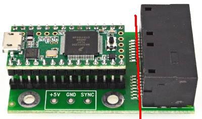
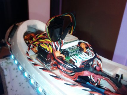
I would like to cut off the RJ45 connectors and simply solder the signal wires directly to the OctoWS2811. Ground and positive wires will be all soldered together to an appropriate power supply.
Am I going to cut something I can't see if I go along the red line in the picture?

Thanks
 

Attachments

  • octo28_adaptor_2.jpg
    octo28_adaptor_2.jpg
    18.6 KB · Views: 92
Yes, it should be ok to cut, as long as you have the soldering skill to connect to the small pads.

The 8 signals connect from the left side, so you shouldn't lose any of the signals.

The 8 ground pins connect from the right side, so all 8 ground wires will disconnect when you cut the PCB. Make your ground connection at the GND pad in the lower center of the PCB, or at any of the 4 mounting holes, and it should work.
 
OK thanks alot.

I did the cut, removed the 8 ground pins completely and then soldered 8 new signal wires that go to 8 radio controlled type plugs. These have 3 wires (pos, neg and signal) so they are perfect cabling to power WS2812b LED strips. 22Ga is sufficient for the lenghts I'm doing. All 9 positive wires solderd together onto my 5V+ source and all 9 ground wires to negative of my power source. 8 strips + 1 teensy/Octo = 9
The pictures don't show wings plugged but all 4 additional strips for the wings work too.

It all works perfectly and very happy of the results. I am total newbie to this world of microcontrollers so thats alot for me to chew at the same time but its nice to be able to just follow tutorials on this site and eventually make something work.

Now I need to learn how to read PWM signals to trigger different light patterns from my radio/receiver. I would love to also be able to dim the whole thing via the radio/receiver with another PWM channel. I have lots of homework to do on this one...

Thanks again.
 

Attachments

  • SANY0007.JPG
    SANY0007.JPG
    103.6 KB · Views: 79
  • SANY0001.JPG
    SANY0001.JPG
    87.3 KB · Views: 108
  • SANY0002.JPG
    SANY0002.JPG
    97.8 KB · Views: 107
  • SANY0003.JPG
    SANY0003.JPG
    99.7 KB · Views: 91
  • SANY0004.JPG
    SANY0004.JPG
    104.3 KB · Views: 101
  • SANY0005.JPG
    SANY0005.JPG
    87.2 KB · Views: 110
  • SANY0006.JPG
    SANY0006.JPG
    104.7 KB · Views: 109
Nice setup!

For ways to read out the PWM the choices range from the simple, using an RC filter and analog read to sample it to the periodic polling of the servo channel and timing the pulse times.

A google around the Arduino forums suggest the command pulseIn is your friend:
http://arduino.cc/en/Reference/pulseIn

Since it returns the length of time a pin was high or low for. Do note that this appears to be blocking, so you are waiting for up to one complete cycle to move on in your code. The Ocoto library should keep running in the background but if you try to read an unconnected input your code will stall unless you set the timeout. Which in this case should be a perfectly fine solution but if you wanted to run a flight control algorithm might not end well.

If timing really is critical then you would use interrupts to track times when the pin inputs changes and log the timer values and use that to determine PWM timings while still allowing concurrent processing.
 
Status
Not open for further replies.
Back
Top