Teensy Humidifier

Status
Not open for further replies.

Constantin

Well-known member
Hi guys,

Some news from my latest project, a whole-house humidifier controlled by a Teensy 3. I got sick of the humidifier my contractor installed because the bottle that the steam is made in has to be replaced annually and the electric bills reach such happy heights that the electric company keeps insisting on sending us fruit platters as a thank you.

My first foray into this was creating a clean water supply, so now we have a very small RO system, which works great. I then installed a Trion CB707 atomizer, which was a bit underwhelming. Not only was the thing loud, it did a great job of slinging lots of water into the ductwork, such that after about 1/2 hour of operation, the ducts had 2x3' puddles in them. While galvanized steel is somewhat water resistant, the ductwork wasn't going to survive that abuse forever.

So, I put on my thinking cap and came up with a ultra-sonic based humidifier that is mounted inside some PVC pieces. These humidifiers are neat in that they include a sensor to prevent them from running whenever the water level is too low. To prevent overflows, I have an oversized drain also. But how to sense water levels? I tried the CAP1188 from Adafruit but quickly realized that it was way too difficult for me to use with a water level sensing application. Teensy to the rescue!

So, I hooked up a Teensy 3 to a number copper strips that I had glued to the outside of the reservoir that the ultrasonic emitter sits on. Based on a regression analysis, I estimate my standard error is on the order of 6mL, which is close enough for me to maintain the water levels inside the reservoir to within 60mL and keep the humidifier happy. So the next step is to verify performance, hook up all the wires, and then install...
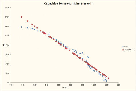
CapSense.png

Nifty... I wonder if it will drift and all that!
 
Last edited:
Cool. What's the intended purpose? For comfort? Does it try to maintain a humidity level or is something you just turn off and on manually?
 
The whole-house humidifier is supposed to keep us at about 35% RH in the wintertime when the house tends to dry out significantly due to the very low exterior RH. Between the whole house air exchange system and the 140-yo old windows, we simply dry out... at 35% RH you're basically right in the right range to limit dust mites, static discharge, etc.

The output of the humidifier is ducted into one of the return ducts on the AC system. When a thermostat calls for humidity, the AC indoor blower turns on and the humidifier starts up. Once the humidity call is complete, the AC blower and humidifier shut down. In the past, this was all accomplished using a 24VAC relay that interfaced with the steam humidifier or the CB707 atomizer. I want to retrofit opts-isolation into the circuit, but no one is offering AC opto-isolator boards that I can see, so I'll have to modify an existing board I have to use that type instead.

Going forward, I want to increase the brains in the AC system, i.e. allow the AC and humidifier fan to run for a few minutes longer after shutting down the ultrasonic humidifier to allow the system to dry out. FWIW, the ducting I'm using is all PVC and can be taken apart easily. A small 24VAC solenoid valve can replenish the reservoir with RO water. The touch system in the Teensy is meant to help regulate the level to maintain a water level of 1cm above the shutoff sensor built into the humidifier.

So far, I am cautiously optimistic as the cap sensor system seems to be doing a good job of identifying the ideal water level and levels above and below. So, hopefully, I won't have to rely on a open-loop control algorithm and focus instead on closed-loop. Time will tell! I'll try posting pics this evening after hooking up the relay board and testing continuous operation.
 
That sounds like a cool project. Someday I'd like to build something similar. It would be interesting to have the intake be switchable from outside or inside air, smart vents, and take into account perception of heat/cold.
 
I suggest you do it in chunks.

My first goal is to get the humidifier to work as expected. Last night, I got the opto-isolated relays to behave as expected, so happiness there. Once the humidifier works, my next goal is improving the whole-house humidifier. Not sure I'll go all out to coordinate the operation as you suggest but some things will hopefully improve.
 
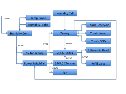
Here is a simple wiring diagram...

In case you want to follow along, here is a diagram showing how I wired this baby up.

Slide1.png

At the front end is a humidity controller I got off eBay that I am happy with. It's basically a safety device that will be programmed for 40% humidity and shut off power if the humidity exceeds that threshold. It features a external humidity sensor and temp sensor on a 3' leash, each.

The controller has a relay that turns on ata pre-programmed humidity and shuts off above. Thus, if the duct work starts getting soggy, all power is cut (due to a bad main AC system blower, miscommunication and so on). For $25, not a bad piece of insurance and you get a free humidity display too. Standby is moderate at around 3W.

Further down, is a 5V power supply and a powerswitch tail.
  • The 5V power supply supplies the Teensy and the VCC for the relay solenoids
  • The Powerswitch tail supplies power to the 24VAC transformer and the fan that helps push moist air into the ductwork.
The relay board activates the humidifier disk and/or the refill solenoid on command from the Teensy. The Teensy has to supply GND, 3.3V, and two lines (active=low). Reminds me of SPI!

The Teensy gets 5V from the 5V power supply, uses three touch sensors.
  • One acts as a reference (GND)
  • One is in the base of the sump and helps pick up / filter the RF interference from the humidifier (Lower)
  • One senses the water level in the reservoir area above the humidifier disc.
Here is still some improvement potential / testing needed. From reading the literature, the TSI is a single unit with a mux, so if you need to filter RF interference (from let's say a noisy ultrasonic generator) then all you can really do is read one reading after the other and subtract. Unfortunately there is no differential mode!!! ;)

Once the Teensy gets a signal that the HVAC system needs humidification, it activates the Powerswitchtail and the fan starts running. Then the Teensy activates the humidifier disc and then refills as needed to maintain a level of 1cm above the sensor on the humidifier disc. Once the call is over, the Teensy runs the fan for a few more minutes to help dry out the piping. Then it waits once more.

If there is interest, I'll post images of the piping.
 
Last edited:
I'm enjoying reading about this project. I'd be happy to see pictures. We could use a dehumidifier in our furnace/boiler area since it is an unfinished space. Maybe I'll follow in your footsteps, so to speak.
 
Very interesting project! I've been trying to get one installed but my HVAC unit is in the attic as it is in many houses here in the southeast US and no one wants to run a waterline up into the attic. Where is your humidifier located ?
 
Apologies everyone for the delay in getting pics up. Everything went together as planned but then I hit a major roadblock with the Sainsmart 2 relay board. The opto-isolator portion works great (on/off as expected) but the relays simply don't get activated, even when the visual LED indicator shows they should. Applying 5V directly from the USB bus makes them jump so I presume it's something wonky in the relay driver side. I give up... buying a new board and will substitute a power switch tail in the meantime.

The good news is that the cap sensor portion is still working great... even after putting the whole assembly together, as opposed to watching it operate in isolation. So now I can watch the level descend as the humidifier operates, with minimal noise in the output. No fancy math, just a division followed by a bitwise shift to decimate.

EDIT: Found the issue with the Sainsmart module. The opto-coupler design is such that 3.3V signals simply don't get the unit very excited. The diode signal is so low, that the relay does not activate. So, took out the 1k drop-down resistor and substituted a 510 Ohm, and now the unit runs happily. Time to write some code to keep the water level at exactly '84'. Which is approximately 1cm over the sensor built into the ultrasonic humidifier.
 
Last edited:
OK, I am going to be adding images from multiple devices, so apologies in advance for the likely need to edit this message a lot. I'll start with a final install pic after I an into some last minute bugs.

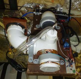
installed.jpg
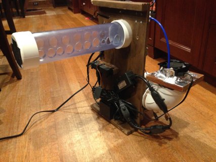
Here is the unit as installed. Note the use of 3" plumbing hardware. There is a fan mounted on a piece of scrap wood on the sweep to the left. Towards the middle, you can see the "Wye" and reservoir I created at its base. The ultrasonic emitter sits down there and a blue line from the solenoid resupplies RO water. The solenoid is to the top left, while the safety shutoff humidity controller is at the top right. It also shows the current duct humidity.

The black wire leading into the plumbing hardware is the power line for the ultrasonic emitter while the clear PVC line coming out is a drain (for the eventuality that the system goes crazy and fills constantly). There are two relays on the Sainsmart board above the Teensy, one relay for the ultrasonic emitter, the other for the refill solenoid. The solenoid can activate for up to 200ms every second, so I limit what it can do...

The Teensy board features two outputs for the relays, an output for the powerswitch tail (that activates the fan and the 24VAC power supply), and an opto-isolated input from the HVAC system (24VAC present = call for humidity). There are three sets of copper ribbons on the plumbing hardware. The one to the left (white wire) acts as a GND, the one in the "knee" of the Wye is the one that senses the height of the water in the reservoir, and the one at the bottom is used to subtract from the reservoir reading (it is a crude filter to get at the interference produced by the ultrasonic system).

So far, so good. A look into the ductwork shows a dry duct... the main house fan is running along and I confirmed that once the K814 no longer gets a 24VAC signal that the Teensy shuts down the powerswitchtail (and with that the 24VAC power supply and the fan). That should limit standby power to less than 5W.

If this protoboard approach works, then I'll come up with something more permanent. BTW, what looks like gray pipe is actually clear. Makes troubleshooting easier.
 
Last edited:
More Pics

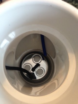
For a view of the Emitter at the Base of the Wye, here an image that is a top view into the Wye:
Emitter.jpg
Down there, you can see the emitter with its assortment of three 20mm ceramic discs that are supposed to last a long time. The black bar is the water level sensor, once the water level reaches that, the sensor shuts off. Ideally, the water level should be maintained 1cm above that bar.

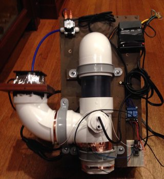
Here is a front view of the assembly. At the top left is the solenoid that lets water into the Wye via the blue tube. In the top right corner is the safety shutoff, aka humidity controller. Between the two is the 90* corner piece that redirects the humid air flow from the vertical into the horizontal.
Front.jpg
Between the 90* turn and the Wye, you can see a clear section of PVC. I opted for that to have a visual indication that the emitter is operating normally. To the left of the wye, you can see a sweep piece with a piece of wood on top. The 120VAC, 4W fan pumps a steady air supply into the wye, directing the moist air from the bottom of the wye through the 90* turn and towards the duct emitter.

On the left side of the wye is the GND tab for the touch system, the thick band in the middle is for level sensing, the one at the bottom is for interference sensing. All have simple protoboard wires soldered to them. The wires end up in a protoboard, along with a Teensy 3.0. The Teensy controls the emitter and the water valve via the modified Sainsmart relays mounted above the protoboard. The Teensy also controls power to the 24VAC power supply and the fan via the Powerswitchtail in the back of the unit.

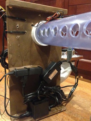
This is the back side, aka the duct side of the assembly. Thanks to choosing the wrong HVAC contractor in the initial phase of the house rebuild, our ducts are very skinny. The lip up top is what hangs the assembly from the top edge of the duct (Galvanized Steel, it can handle the weight).
Duct Side.jpg
Below the lip, you can see the emitter tube that reaches into the duct. It's quite perforated, but only on the sides, to ensure that most condensate can flow back into the wye / sump. The emergency shutoff sensor can be seen dangling down (yellow/red/black wire). The triplex strip is the power supply coming from the emergency shutoff controller. This power strip is what the Teensy 5V power supply plugs into (not shown here), along with the powerswitchtail. The powerswitchtail can be seen to the right, with the 24VAC power supply below. A power splitter plugs the fan and the 24VAC power supply into the powerswitchtail.

The assembly slides from the side of the duct, with he holes aligned with the direction of the air flow. I verified that a lack of air flow quickly triggers the shutdown controller. Incidentally, the controller was also allergic against having the sensor mounted near metal- the indicated / sensed humidity would descend towards zero, then "EEE" shows up. By mounting the sensor on the emitter tube away from the duct metal, it operates fine. The air flow is so great, that the indicated humidity stays very low, i.e. teens. Without airflow, it quickly rises and shuts down.

Here is a view from the other side.
Duct Side 2.jpg
I have no holes in the top of the emitter tube to limit debris entering the tube from the register above. The clear tube also lets me visually inspect the condition of the system. Since the lip holds the assembly, only a single lag screw is needed to secure the assembly to the duct work. Other than a slight tinkling sound and a small whirr of the fan, it is virtually silent as it operates.

FWIW, the assembly can be taken apart for cleaning, maintenance, etc. The cap on the perforated pipe, the 90* turn, and the clear sections are glued together. However, this pipe assembly is not glued into the wye . No need to, as the wye is wider than the tube fitting into it, and gravity takes care of the rest (water doesn't generally run uphill w/o a good reason).
 
Last edited:
So far, the system has been working great. Though the rise in humidity inside the home is slow, it is steadily improving, and not unlike the performance of the steam humidifier. With perhaps one tiny difference, i.e. the consumption of 60W, not 2000W.

Granted, the addition of moisture is going to lower the home temperature and require the boiler to operate longer, but the net cost of gas being burned vs. blowing through boatloads of electricity is not comparable. Besides, our home system is converting that gas to heat at ~98% efficiency while the power plant is lucky to get 35% unless it has a local need for low grade heat (aka combined cycle systems, CHP, and so on).

So, at 1-2% per day, our RH is rising. In another week or so, we should be back to 35%.

... and though it might seem like sacrilege to use a Teensy this way, it does work! Some day I may add a Nokia display or some such to make use of more I/O pins. Also, I have a ACS712 that I want to integrate into the controller to sense when the humidifier emitter is not operating even when its relay turns it on. This will help deal with conditions like a severely undefilled reservoir which may not trigger a refill response due to the way the touch sensor is working.
 
Last edited:
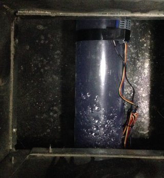
Last but not least, a picture from inside the duct. This is a top view, i.e. through a floor register. The air flow is down towards the emitter tube, followed by a sharp turn to the left.
In duct.jpg
After two days of operation, there are two drops of water on the duct floor. Otherwise, all is dry. If this turns out to be a consistent issue, I'll put a piece of plastic down there for the water to sit on and evaporate. These two drops are nothing compared to the 100x larger puddles that the CB707 produced.

I had two portable evaporative units left over from past attempts to keep the kids comfortable, etc. and then deployed them. As a result, the home humidity is raising more rapidly. The house is drinking it up, several gallons have been absorbed. Now we're up into the 30's and then the whole-house humidifier will be able to maintain the desired levels.
 
Last edited:
This is terrific Constantin, I hope to get to this stage soon. That is, I enjoy diddling with new sensors etc and making appallingly small add-ons but I have yet to use the technology to solve real problems around the house. I have made dark-activated night lights which are in constant use but these are more or less passive. And I have made quadcopters, but these are really just toys. My environmental sensor/RTC will likely be the first really useful device I build with the Teensy that I will turn into a product for my household use, likely as a wall clock. I also will use it to monitor the garage and maybe use it outside. But a device that solves real problems for people is the epitome of the design art. Congratulations!
 
Very interesting project! I've been trying to get one installed but my HVAC unit is in the attic as it is in many houses here in the southeast US and no one wants to run a waterline up into the attic. Where is your humidifier located ?

This humidifier design does not need a duct install to work in your home. Mine is installed in the main return inside the basement (which virtually do not exist in the South), but I could install it in our attic, if I wanted to. The key thing being that the attic space in our home is conditioned, i.e. it never freezes.

US Attic installs are frequently problematic due to the 'cold roof' design that is prevalent here. The next time you have to pull your roof off, consider installing 4-6" of XPS on the outside and converting the roof to a so-called 'hot roof' instead. Not only does it help mitigate the stack effect inside homes, but it gives you more usable space too. FWIW, the 'cold roof' spec was developed by the US Army in WWII and was completely debunked by Building Science Corporation in the 1990's. However, now so many generations of builders and inspectors have gotten used to a cold roof that you have to request a 'hot roof', even though it works better!

In Germany, boilers are now frequently installed in the so-called attic space (usually as part of a bathroom, all 'attic' space in new construction is now fully finished). Not only is this design better for burping the air out of the hydronic system (which is how 99% of EU homes are heated), but it also limits the amount of flue pipe, etc. that has to be installed which increases the usable space inside the home. Boilers in basements are an anachronism going back to the coal days.

Anyhow, you can likely install this unit anywhere, as long as the water is conditioned well. I chose this design because I wanted a low maintenance solution to an ongoing problem, i.e. keeping my home at 35% RH in the winter. The steam humidifier was a PITA thanks to its insane energy demand (hence the fruit platters), the annual bottle replacement ($130), and the slow but steady leakage past OEM seals that was corroding the unit from the inside out (this is a problem with steam humidifiers, they are great at producing brine).

To keep the humidifier happy, I installed an RO system, which should remove the vast majority of solids (via a 20, 1, and 0.5 micron filter) and ions (98% via the RO membrane). I did not opt for a DI post-polish option, though a non-duct/'open air' installation may benefit from that (the cost delta is not great, I just didn't want the additional maintenance, cost). For a open-air installation, I would consider the DI option, it helps keep the dust down. Also, by installing this unit in a return duct, I ensured that the air stream gets filtered by a HEPA filter, further reducing the dust issue.

For a slab on grade home, you could likely mount the RO/DI system under the kitchen sink, run the ¼" line up a cabinet and then mount the unit on top of a cabinet. Feasibility depends on the height of your ceilings vs. the cabinetry, tolerance of the missus re: 'engineering' marvels, and so on. Or, mount the unit somewhere inside the conditioned space where it is close to the return duct entrance.

You could likely omit the 90* turn and the long length of horizontal, perforated pipe by simply using a 12-18" section of straight pipe inserted vertically into the Wye. You do need a little straight section though, as a ultrasonic humidifier will occasionally produce fat drops that have to corralled back into the sump instead of making the surroundings wet.

Last but not least, consider simpler options. My first DIY ultrasonic humidifier uses a float valve for filling it with RO water, a floating emitter disc, a fan, and the $25 eBay controller. The system is housed inside a plastic rectangular kitty litter box, features a drain, and is designed to use condensate from an AC system as fill water also. I can post pics, but it's pretty rude and crude. For example, the fan benefits from not having water droplets hit it. So it's mounted to the kitty litter box lid from above while a recycled soup container shields it from water droplets from below...
 
Last edited:
This is terrific Constantin, I hope to get to this stage soon. That is, I enjoy diddling with new sensors etc and making appallingly small add-ons but I have yet to use the technology to solve real problems around the house... But a device that solves real problems for people is the epitome of the design art. Congratulations!

You are too kind! :D

Not convinced this is art - my parents used to sell that. :p

However, I'd be happy to point anyone towards the components used in this build if it's of interest.
 
Working on next iteration - first worked but was not powerful enough. Now working on 12 emitter version.
 
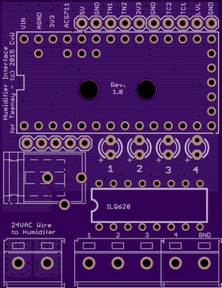
... and the interface board is off to OSH. Sat down and finally did it.

large_i.png

This is the topside. I've designed it for Teensy 3.x as well as for Teensy LC use. It features a few wanted improvements, such as

1. a current sensor (to see if the humidifier is out of water)
2. two touch inputs (for capacitive water sensing) or a level switch input (w/pullup resistor)
3. a series of pins that allow the Teensy to connect directly to a cheap dual relay board
4. a breakout for a potential RS485 interface
5. four zone handler inputs to call for humidity. These inputs are opto-isolated and feature a external LED when active. Instead of a fat wire terminal, I suppose I could have gone for a RJ45 plug.
6. Dual power supply - either USB or external 5.5x2.1mm plug @ 5V.

Will be interesting to measure the currents involved. The PS claims to have 300W of capacity and the transformer is pretty darn heavy. I stitched both sides of the PCB together with 200 mil wide polygons to carry the current. However, I do have my doubts re: the ability of these tiny Allegro ACS chips to handle the currents they're rated for.

For the picky folks out there doing some pixel-peeking, I realize that the LC doesn't have a external AGND pin. Thus, for the LC, there will be less of a benefit re: the current layout. But if someone wanted to use a 3.x series, then there is a proper AGND plane under the analog signals.
 
Last edited:
Consider incorporating outside temperature. On very cold days and with older windows, you will get condensation unless you cut back on interior humidity.
 
I messed this iteration up. So OSH is making the next one before I even received it. The pads for the ACS711 were incorrect and I didn't notice until yesterday! Argh. At least I noticed the issue before the thing made it to me. So, another $14 to OSH and another week for the stuff to get fabricated. Oh well!
 
More progress... more iterating.... my latest PCB had some sort of short in the 5VDC supply, may be related to a inverted Diode, for all I know. Anyhow, biggest learning in this round was: if you want to use capacitive touch for a water level measurement application, the whole rig has be grounded very well. For example, the output from the touch sensing could go up or down 2000 points based on whether I attached a computer to the USB port of the Teensy and then touched the computer (while standing on a concrete slab), etc. Once I abused the home heating system as a earth ground, the touch measurements became immune to that kind of interference and the rig behaved consistently well re: refilling the water into the tank.

Even though the current prototype rig is finally functional, I am running one more OSH park PCB turn to finalize it (I know, famous last words). For example, I want to use 25A-rated relays with built-in quick connects for the ultrasonic connection since the seller claims that the thing can pass 10A of current. The seller also claimed that the thing included a 24VAC power supply (unregulated) whose real output is actually 36VAC.. so the water solenoid valve is definitely getting warm thanks to 'enjoying' a power supply 50% higher than spec... thankfully, I was able to source a 36VAC solenoid valve from China... and in the meantime, the duty cycle is low enough that the valve is surviving.
 
Status
Not open for further replies.
Back
Top