Coming Soon: Teensy-LC (low cost Teensy)

Status
Not open for further replies.
Isn't that on the USPS side Robin? I can also see my Teensies 3.1 have departed from the US yesterday. Will try to see if that also works within NL.
Update: nope, doesn't work in NL yet. Guess we should have just have stayed German territory after all in 1945 ;)

It really varies by country. There have been improvements all around. The US is able to provide more info as it receives it from other countries. Many countries have improved their tracking by using the customs label bar code as a tracking number. More complete tracking info can sometimes be found on the USPS web site, the postal web site for the destination country, or the customs web site for the destination country.
 
Dutch postal service isn't very reliable anymore, I have had very strange situations with packages from China (one time they said customs (read: their own customs department) could not read my address since the package was severely damaged, the next week when I called they said they had returned it to China. Another week after that I got the very same package with a well readable address and no damage at all). Fortunately they seem to be better in handling envelopes with Teensies :) at least... until now.
 
I see, I work in a "Fachhochschule" (university of applied sciences) two days in a Nursing school and the rest in the Computer Science department, try to link healthcare and technology (thus using teensies for CPR training etc).

Very convenient that the LC has two easy accessible i2c ports, one to connect to the rest of the system, and one to connect to a bunch of sensors (we make a modular system), hope that helps in improving CPR / nursing performance in the near future.
 
So far it's working well, I'm just struggling with my code a bit.

The board just works:
  • plug it in for the first time -> blinky
  • write own blinky sketch and hit download -> loader works fine
  • even more blinky without problems

DmaSpi seems to working fine. When I'm sure that it actually does work fine I'll push it to github.
 
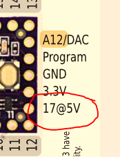
I'm not sure what 5V is at issue - VIN is declared as (3.7 to 5.5 volts) on Pinout card - this Technical Specifications table on product page (screen snip above) shows:
Digital I/O 27
Voltage Output 3.3V + one 5V
Current Output 5mA + four 20mA
Voltage Input 3.3V Only

Product page

Pinout detail

Note: I don't think this was the issue but misreading this part of the pinout card might not say "VIN output on pin #"'17 @5V' but rather wrongly suggest 17 pins usable at 5V
tlc_17.png
 
Last edited:
Maybe the pinout card should say something like "17 @VIN Voltage"? That's kinda long, but maybe "Voltage" could be a smaller font and squeeze underneath?

Near the end of next week I need to finalize the card and get them printed, so we'll have cards when Teensy-LC releases in March. I'm open to ideas. Just speak up now, since the card design gets finalized in a matter of days....
 
As I mentioned back in posts #238 and #241, I think CS pins may need to marked for which buss. Also some alternative pins maybe should be included as well...
 
Maybe the pinout card should say something like "17 @VIN Voltage"? That's kinda long, but maybe "Voltage" could be a smaller font and squeeze underneath?

Near the end of next week I need to finalize the card and get them printed, so we'll have cards when Teensy-LC releases in March. I'm open to ideas. Just speak up now, since the card design gets finalized in a matter of days....


About that, although I know it might be a bit cumbersome for processing, but wouldn't it be a good idea to get selection option that says "include card" on checkout in your store. I like the cards, even have some taped above my working place, but I consider it a loss that I have a whole stack of them now (environment etc. and it would be a shame to just put such a beautiful cards in the waste bin).
 
Maybe the pinout card should say something like "17 @VIN Voltage"? That's kinda long, but maybe "Voltage" could be a smaller font and squeeze underneath?

That does seem clearer. Its a boosted copy of pin17. Maybe it should be labelled differently, with an explanation in a callout box.

Edit: the rear photo posted earlier shows that pin labelled on the silkscreen as 17-5V. Also the DAC pin as 26-DAC. Does that mean that on the LC the DAC pin can be used as a digital I/O pin as well as analog input A12 and DAC out?

Near the end of next week I need to finalize the card and get them printed, so we'll have cards when Teensy-LC releases in March. I'm open to ideas. Just speak up now, since the card design gets finalized in a matter of days....
I was going to revise the card I made to include higher resolution front photo and also a card for the back (showing the inner pins). However, I don't have clean photos of green board teensyLC and I don't have a board to photograph myself. There were some higher resolution front and back photos posted earlier, but those were purple boards and would need some straightening and background knockout to be useable.
 
Last edited:
Also on the subject of pinout cards, there have been several postings over the last few months where people misread the rear pinout card to mean that the outer pins were different top to bottom (and were confused because surely they will join together if you solder pins to them). Having lines going from the labels to the inner pins (and pads, for Teensy 3.0/3.1) would seem to aboid that confusion.
 
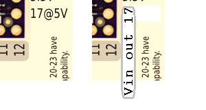
It should get it's own color cue? Is p17 5v input tolerant - or just output VIN only? My thought was to invert logic order as in: "Vin out p17". Since the label item isn't near the pin #17 - the context isn't there like the other labels.
 
defragster: The pin on the back on the LC where Vbat used to be on the 3.0/3.1 is an output only pin (i.e. there is a one way MOSFET between the pin 17/A3 and the back pin). If you want to read from it, you need to hook up the connection the pin 17/A3 directly. That means it is not 5v tolerant. Paul answered this a few pages ago.

The intent is to allow you hook up a single low powered servo or a ws2812b (neopixel) directly to the pin without needing to use a level converter. You would then hook up the remaining 2 wires on the servo/ws2812b to the ground and the VIN pin (not the 3.3v pin that is next to the back pin), Thus the control is done through A3 in the source, and neopixel/servo gets its power from the VIN pin. It would have been more convenient if the back power pin was also VIN and not 3.3v (so you could hook the servo/ws2812b directly to the 3 adjacent pins), but it itsn't that hard to run a wire from Vin.

<edit>
You probably don't want to run a high power LED from this pin, as the pin can only deliver 8mA of power.
 
Last edited:
I did know Output Only from scanning so sort of a rhetorical ? just showing how much it takes to describe - there are two pin #17's and one is very special and 5 characters comes up short

@Paul: Odd too that 17/A3 is 20mA and 5Vp17 is 8mA - electrically sensible - but so many details. Question how much current does it take to drive that p17 Mosfet? If you take 3.3v@20mA off 17/A3 is there any chance the Mosfet won't properly fire 5V off p17?

MM: thanks as I read that I didn't look at the pinout to visualize 2 pin 17's.

[edit]: @addressing in forum - pardon my generally untrained etiquette
 
Last edited:
Ok, let's see if I can get all of today's questions answered in just 1 post....

I think CS pins may need to marked for which buss.

Yes. Since there aren't 5 logically different hardware-controlled CS pins, maybe just "CS0" and "CS1" will work?

I'll be working on the final card design later this week. Hopefully there'll be time to post a couple draft copies for feedback.


wouldn't it be a good idea to get selection option that says "include card" on checkout in your store.

Right now, messing with anything on the website is the last thing I should be doing. Eventually it needs a huge amount of work, but that should happen some time when a new product isn't about to release.

Customizing stuff is something we're not set up to do. I've often considered setting up a way to order different pins & sockets soldered, with a few days lead time. But logistically, it really makes things much more complex. We do pretty well with shipping orders quickly, but only because we try to keep everything as simple as possible.

If you *really* want to not get a card included, you can mention that in the "additional instructions" box. Some people do exactly that when ordering 10 or so.


Also the DAC pin as 26-DAC. Does that mean that on the LC the DAC pin can be used as a digital I/O pin as well as analog input A12 and DAC out?

Yes, on Teensy-LC the DAC pin can also work as digital I/O or an analog input.

On Teensy 3.1, the DAC pin can be an analog input, but not digital I/O.


I was going to revise the card I made to include higher resolution front photo and also a card for the back (showing the inner pins). However, I don't have clean photos of green board teensyLC and I don't have a board to photograph myself.

I'll update the web page soon, with a better photo of the green board.


.... with a suggestion that using 100mA is a safe design rule for the Teensy 3.0. What is the appropriate value for the LC?

For now, I believe recommending 100 mA is still probably best. Teensy-LC will use less power than Teensy 3.1, and the on-chip regulator has similar specs, so in theory a little more current could be available.

For initial release next month, I'd prefer to keep things conservative, specs-wise.


Having lines going from the labels to the inner pins (and pads, for Teensy 3.0/3.1) would seem to aboid that confusion.

Oh, the Teensy 3.1 printed card was updated months ago, but it seems the reference page on the website has the older version of the card.


I find the term @5V confusing due to the ampersand.

What specifically would be more clear?


I did know Output Only from scanning so sort of a rhetorical ? just showing how much it takes to describe - there are two pin #17's and one is very special and 5 characters comes up short

Yeah, with any sort of reference card, or pretty much any type of graphic intended to convey technical details, there's a trade-off between expressing accurate details versus maintaining overall simplicity that allows the most important features to be seen easily. I'm afraid there are no perfect answers, only (somewhat) reasonably compromises.

Question how much current does it take to drive that p17 Mosfet?

It's a CMOS logic chip, not just a mosfet. Internally, it's made of many mosfet transistors inside the chip, but functionally it's a logic gate chip, not a mosfet transistor.

Like all such logic chips, the input current is minimal. The input is a very low capacitance, under 10 pF, not anything like the large capacitance of a single high-power mosfet transistor. Like all capacitive inputs, some current is needed during the rising and falling edges to switch the logic state, but with such a low capacitance, it's really not worth much concern. To maintain a steady logic state on a capacitive input requires no current at all.

For all practical purposes, the buffer doesn't "use up" any significant portion of the 20 mA current the main chip can provide on pin 17.
 
It should get it's own color cue? Is p17 5v [3.3v] input tolerant? My thought was to invert word order as in: "Vin out p17". [edited]

Paul: Thanks. How about a Grey color Digital loop/ring around the label on the end p17 description - vertically for more room?

p17label.png

Re: voltage on p17 - in the case it was confused for the input A3/17 pin? Like my 'current drive' question - if it can't be expected to be a problem then special warning isn't needed.
 
I find the term @5V confusing due to the ampersand.


me too. not sure much is won by trying to find a as-short-as-possible but ultimately cryptic label.

as long as there aren't that many special cases, i'd suggest marking the pin as somehow special, using a different color and some sort of familiar typographical device, eg. an asterisk '*' or obelisk '†'. a more verbose description could then be included in some legend/footnote.
 
Last edited:
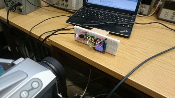
While I was working on DmaSpi I noticed that the chip seems to get pretty warm, so I placed my breadboard in front of our IR camera

DSC_0183.jpg

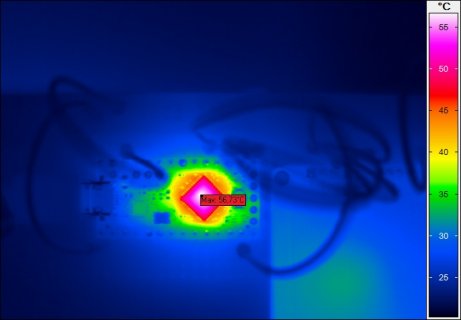
And the result:

04_CAM23132809.jpg

The chip is doing some graphics and sending data to an OLED display (you can see the display on the right). This is without any detailed knowledge about the emissivity of the chip's surface, which will be less than 1. Therefore the chip's surface temperature is probably above 60 °C. I don't have pictures of the 3.x boards, but they didn't seem to get this warm.
 
Status
Not open for further replies.
Back
Top