Coming Soon: Teensy-LC (low cost Teensy)

Status
Not open for further replies.
Try "sub" instead of "subs".

Really, the assembler should accept "subs", since the status bits are always updated. But this looks like a quick in the assembler.

But you'll need a #ifdef, to use "sub" on Teensy-LC and "subs" on the others. Yeah, it's messy.


I found that if you look at the disassembly of the asm for delayMicroseconds it uses 'subs' :confused:

Code:
00000472 <L_10_delayMicroseconds>:
     472:       3b01            subs    r3, #1
     474:       d1fd            bne.n   472 <L_10_delayMicroseconds>
     476:       4770            bx      lr
     478:       00027100        .word   0x00027100

I had some issues with this and other instructions that try to set flags for inline assembly.

The assembler complains with this error
Error: instruction not supported in Thumb16 mode -- `subs r3,#1'

I don't know gcc/gas arm syntax or I'd fix it myself.
You can use asm (".syntax unified"); before the subs instruction and then asm (".syntax divided"); after it and it will compile so something like this would compile:
Code:
static __inline__ void      /* exactly 4 cycles/loop, max 2**32 loops */
_delay_loop_2_x( uint32_t __n )
{                                               /* cycles per loop      */
    __asm__ volatile (                          /* __n..one        zero */
                "L_%=__delay_loop_2_x:"               "\n\t"
                ".syntax unified"                     "\n\t"
                "subs   %0, #1"                       "\n\t"
                ".syntax divided"                     "\n\t"
//                "nop"                               "\n\t"
                "bne    L_%=__delay_loop_2_x"         "\n"
                : "+r" (__n) :
    );
}

the disassembly looks good to me:
Code:
00000476 <L_19__delay_loop_2_x>:
     476:       3b01            subs    r3, #1
     478:       d1fd            bne.n   476 <L_19__delay_loop_2_x>
     47a:       4770            bx      lr
     47c:       00002710        .word   0x00002710

 
I found that if you look at the disassembly of the asm for delayMicroseconds it uses 'subs' :confused:

Yes, it's absolutely terrible.

But that's the way the toolchain is, where you have to write "sub" which really means "subs" (it does in fact update the status bits) and gets disassembled as "subs".
 
Yes, it's absolutely terrible.

But that's the way the toolchain is, where you have to write "sub" which really means "subs" (it does in fact update the status bits) and gets disassembled as "subs".

WOW. That sucks. Seems like a tool bug to me, since the assembler and the disassembler don't agree on the mnemonics.
I can't imagine the amount of time wasted spent trying to figure that one out.

That fixed it.
Is there a better define rather than using the processor define of __MKL26Z64__ to indicate that "thumb" mode
is being used and "sub" must be used instead of "subs"
i.e. I'd like to test a define that works on any ARM processor using thumb mode vs just this specific one to put this
code to bed vs having to fix it later in the future.

--- bill
 
I believe in the full ARM instruction set there is both SUB (does not set condition code fields) and SUBS (does set condition code fields). However in thumb16, there is only SUB and it sets the condition code fields always. The GCC compiler defines __thumb__ and __thumb2__, depending on which thumb instruction set is used.
 
Have some questions on pin i/o.
Maybe this isn't the best thread for this, but I'll start off here.

Currently openGLCD jumps through lots of hoops to try to do the fastest
pin i/o as possible. On the AVR that drops down to direct port i/o and can
even do multi bit nibbles or even byte i/o when possible.
On the Teensy arm processors, it uses digitalReadFast()/digitalWriteFast() which
are a bit faster than digitalRead()/digitalWrite() but no where near
as fast as the raw port i/o on the AVR even thought the AVR overall is a
significantly slower processor.

So the first question is:
Is there a better form of pin i/o available on the teensy arm based products?

The second question is:
Is there way other than having to check for CORE_TEENSY and then the processor types
to detect when digitalReadFast()/digitalWrite() exists?
i.e. on other platforms those are implemented as macros so I can simply check for
their existence but on Teensy they are implemented directly as inline functions so you
can't check for their existence.


--- bill
 
I believe in the full ARM instruction set there is both SUB (does not set condition code fields) and SUBS (does set condition code fields). However in thumb16, there is only SUB and it sets the condition code fields always. The GCC compiler defines __thumb__ and __thumb2__, depending on which thumb instruction set is used.

So it looks like __thumb__ is the defined when using thumb16 where "subs" can't be used.
Thanks.

Another question, out of curiosity, is thumb16 a locked in mode for a given processor or is something that
can change depending on how the code is compiled through command line or optimization options?
--- bill
 
I don't really know the arm all that well, but I believe it depends. Some processors are ARM-only, some are Thumb-only, and some can have ARM/thumb code in the same context, and use a mode context swap instruction to switch between the two.
 
I don't really know the arm all that well, but I believe it depends. Some processors are ARM-only, some are Thumb-only, and some can have ARM/thumb code in the same context, and use a mode context swap instruction to switch between the two.
Great so using the __thumb__ define is definitely the way to go vs using a processor define.

Thanks again.

--- bill
 
One thing I still need to get resolved is can the LC 3v pin inputs tolerate a 5v output when fed through a 10k series resistor
like the Teensy 3 could?
 
All Cortex-M chips are thumb instructions only. If you ever try switch to ARM state, the processor goes to fault mode.

Cortex-M0+ supports only the v6m instructions. Cortex-M3 and Cortex-M4 support the much larger v7m instruction set, and M4 adds the special DSP instructions.

I too would like to know if there's a reliable set of gcc built-in defines to distinguish between all these cases.
 
One thing I still need to get resolved is can the LC 3v pin inputs tolerate a 5v output when fed through a 10k series resistor like the Teensy 3 could?

Yes, it can.

As with Teensy 3.0, the caveat is the total injected current on all pins must always be less than the current consumption of the entire chip. Rarely is this an issue while the chip is running, but you have to be careful if using the very low power modes.
 
All Cortex-M chips are thumb instructions only. If you ever try switch to ARM state, the processor goes to fault mode.

Cortex-M0+ supports only the v6m instructions. Cortex-M3 and Cortex-M4 support the much larger v7m instruction set, and M4 adds the special DSP instructions.

I too would like to know if there's a reliable set of gcc built-in defines to distinguish between all these cases.

Just as a followup, __thumb__ is defined when building for Teensy 3.0 and for Teensy LC so that define isn't the magic bullet.
--- bill
 
My headers define KINETISK and KINETISL. That's hardly as authoritative as a gcc builtin, but so far I've been going with those.
 
Missing error information

Just ran into a strange issue in the 1.21-beta6 on the 1.6 IDE
There seems to be an issue with the error output when building for teensy boards.
I see this when a #error is encountered.
If I build for uno, I can see what I expect and the useful information like the file, line number, and error message is at the bottom
of the red output. When I build for any teensy board the output is truncated and I am not getting the error information.

I tossed a #error into a header file and this is what I get when building for Teensy++/Teensy 3.0 or Teensy LC: (all teensy boards)

Code:
Arduino: 1.6.0 (Linux), TD: 1.21-beta6, Board: "Teensy 3.0, Serial, 96 MHz (overclock), US English"

Build options changed, rebuilding all
Using library openGLCD in folder: /media/UbuntuRoot/home/bill/Arduino/Arduino-AVR/libraries/openGLCD (legacy)

/media/DataPartition/2B-Organized/devel/avr/arduino/arduino-1.6.0-bap/hardware/tools/arm/bin/arm-none-eabi-g++ -c -g -Os -Wall -ffunction-sections -fdata-sections -MMD -nostdlib -fno-exceptions -felide-constructors -std=gnu++0x -fno-rtti -mthumb -mcpu=cortex-m4 -D__MK20DX128__ -DTEENSYDUINO=121 -DARDUINO=10600 -DF_CPU=96000000 -DARDUINO_ARCH_AVR -DUSB_SERIAL -DLAYOUT_US_ENGLISH -I/media/DataPartition/2B-Organized/devel/avr/arduino/arduino-1.6.0-bap/hardware/teensy/avr/cores/teensy3 -I/media/UbuntuRoot/home/bill/Arduino/Arduino-AVR/libraries/openGLCD /tmp/build1859051540936981105.tmp/GLCDdiags.cpp -o /tmp/build1859051540936981105.tmp/GLCDdiags.cpp.o 
In file included from /media/UbuntuRoot/home/bill/Arduino/Arduino-AVR/libraries/openGLCD/include/glcd_Device.h:36:0,
                 from /media/UbuntuRoot/home/bill/Arduino/Arduino-AVR/libraries/openGLCD/include/gText.h:36,
                 from /media/UbuntuRoot/home/bill/Arduino/Arduino-AVR/libraries/openGLCD/include/glcd.h:41,
                 from /media/UbuntuRoot/home/bill/Arduino/Arduino-AVR/libraries/openGLCD/openGLCD.h:5,
                 from GLCDdiags.pde:45:
Error compiling.

And this is what I get when building with the exact same IDE but for UNO:
Code:
Arduino: 1.6.0 (Linux), TD: 1.21-beta6, Board: "Arduino Uno"

Build options changed, rebuilding all
Using library openGLCD in folder: /media/UbuntuRoot/home/bill/Arduino/Arduino-AVR/libraries/openGLCD (legacy)

/media/DataPartition/2B-Organized/devel/avr/arduino/arduino-1.6.0-bap/hardware/tools/avr/bin/avr-g++ -c -g -Os -w -fno-exceptions -ffunction-sections -fdata-sections -fno-threadsafe-statics -MMD -mmcu=atmega328p -DF_CPU=16000000L -DARDUINO=10600 -DARDUINO_AVR_UNO -DARDUINO_ARCH_AVR -I/media/DataPartition/2B-Organized/devel/avr/arduino/arduino-1.6.0-bap/hardware/arduino/avr/cores/arduino -I/media/DataPartition/2B-Organized/devel/avr/arduino/arduino-1.6.0-bap/hardware/arduino/avr/variants/standard -I/media/UbuntuRoot/home/bill/Arduino/Arduino-AVR/libraries/openGLCD /tmp/build1859051540936981105.tmp/GLCDdiags.cpp -o /tmp/build1859051540936981105.tmp/GLCDdiags.cpp.o 
In file included from /media/UbuntuRoot/home/bill/Arduino/Arduino-AVR/libraries/openGLCD/include/glcd_Device.h:36:0,
                 from /media/UbuntuRoot/home/bill/Arduino/Arduino-AVR/libraries/openGLCD/include/gText.h:36,
                 from /media/UbuntuRoot/home/bill/Arduino/Arduino-AVR/libraries/openGLCD/include/glcd.h:41,
                 from /media/UbuntuRoot/home/bill/Arduino/Arduino-AVR/libraries/openGLCD/openGLCD.h:5,
                 from GLCDdiags.pde:45:
/media/UbuntuRoot/home/bill/Arduino/Arduino-AVR/libraries/openGLCD/include/glcd_io.h:1:2: error: #error XXX
 #error XXX
  ^
In file included from GLCDdiags.pde:47:0:
/media/UbuntuRoot/home/bill/Arduino/Arduino-AVR/libraries/openGLCD/include/glcd_io.h:1:2: error: #error XXX
 #error XXX
  ^


There must be some sort of output error parsing that is different for Teensy that is dropping the information.
It is pretty important information so obviously it needs some tweaking.


--- bill
 
Yes, it can.

As with Teensy 3.0, the caveat is the total injected current on all pins must always be less than the current consumption of the entire chip. Rarely is this an issue while the chip is running, but you have to be careful if using the very low power modes.

Something is different with the LC vs the 3.
I tried using 10k series resistors instead of the level shifter and the LC
doesn't seem to be a able to reliably read the 5v signal levels which
ends up putting trash on the display.
I don't believe it is a timing issue as the Teensy 3.0 works even when clocking at 96Mhz and I've also forced the LC
to use the much slower Arduino delayMicroseconds() call which should give much longer than needed delays.

If I turn off all data reads, and use the write cache, then it works fine with the LC so the issue is definitely
on the read side.

I've also tried dropping back to standard digitalRead()/digitalWrite() instead of the "fast" versions
and no difference.

I'll hook up a logic analyzer and report back but I'm not expecting an issue with the delays.
I don't have a scope so I can't look for analog type corruption on the signals.

Any ideas?

--- bill
 
Something is different with the LC vs the 3.
I tried using 10k series resistors instead of the level shifter and the LC
doesn't seem to be a able to reliably read the 5v signal levels which
ends up putting trash on the display.

--- bill

tell me more. are you using INPUT_PULLUP on teensy side? how fast is input signal changing? what is source of 5v signal?
 
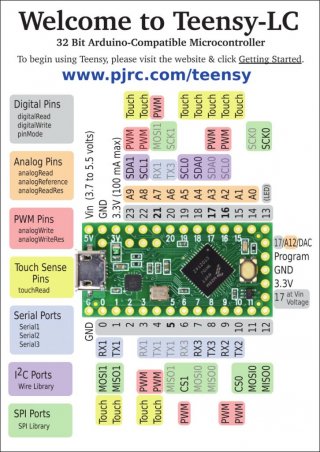
Here is a first draft for the front side of the reference card.

card6a_rev1.jpg
 
Why are the labels for pins 5, 16, 17 and 21 bold?

There is hardly any difference in the colors for digital pins and serial ports - maybe make it more prominent?
 
Here is a first draft for the front side of the reference card.

On 3.* cards, pin between Vin and 3.3v was marked as AGND

and shouldn't A12/DAC be 26 not 17?

the red dots for 20ma pins was nice addition as per Nantonos draft, though I guess your bold for 5,16,17,21 conveys that info (steganography)
 
Last edited:
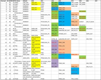
There are probably a few other alternate pins that potentially could be marked. Example CS on pin 2?

Also my built table could be wrong, but wondering about PWM on pin 21?

Teensy-LC---Pin-out.jpg
 
Status
Not open for further replies.
Back
Top