Hi all, please help me.
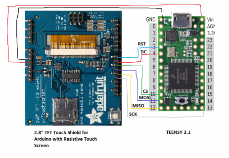
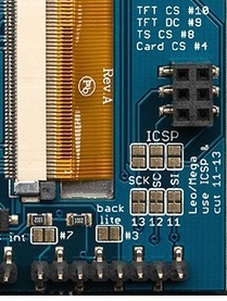
I bought '2.8" TFT Touch Shield for Arduino with Resistive Touch Screen' from adafruit.com and want to connect to TEENSY 3.1. Wired follow by scheme (see below). For this I used library 'Adafruit_ILI9341-master' somewhere from github. But display just shine. Can someone help me to check scheme, if all necessery pins are used? and also the library is correctone?
thanks for help
piece of code from graphicstest.ino is:
// For the Adafruit shield, these are the default.
#define TFT_CLK 13
#define TFT_MISO 12
#define TFT_MOSI 11
#define TFT_CS 10
#define TFT_DC 4
#define TFT_RST 3
// Use hardware SPI (on Uno, #13, #12, #11) and the above for CS/DC
//Adafruit_ILI9341 tft = Adafruit_ILI9341(TFT_CS, TFT_DC);
// If using the breakout, change pins as desired
Adafruit_ILI9341 tft = Adafruit_ILI9341(TFT_CS, TFT_DC, TFT_MOSI, TFT_CLK, TFT_RST, TFT_MISO);
void setup() {
Serial.begin(9600);
Serial.println("ILI9341 Test!");
tft.begin();