Teensy 3.1 analog inputs - explanation

Status
Not open for further replies.
Hi!

I'm making MIDI drums with about 20 piezo sensors. Teensy 3.1 have 21 analog inputs.

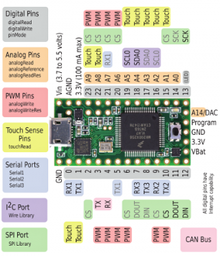
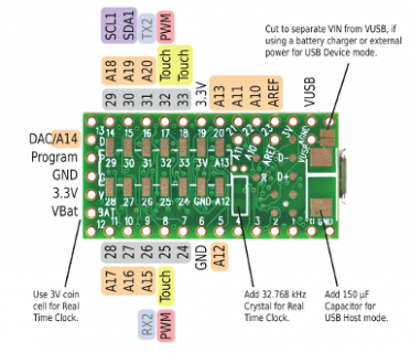
I don't understand part of pinout diagram:
A18 = A0
A19 = A1
A20 = A2

I will be grateful if someone can explain me that.
Also, should I use Zener (3.3 V) in parallel with the piezo or just 1 MOhm resistor?
 
I think you are confused when you look the top pin out and the bottom pinout.

The top pinout is for the headers, that most of the time you would usually solder male pin headers.

teensy31_front_pinout.png

The bottom pinout is for the pads (on the middle of the board), you can solder wires to it or use a breakout board to access it.

teensy31_back_pinout.png

I never played with piezo sensors so I can not help you with that question.

Vitor Henrique
 
If you hit the piezo hard, it can generate quite high voltages. It is unlikely these can have enough energy to damage the Teensy, but either a 1 Meg in series or a zener in parallel would work. The risk with the zener is that if the Teensy isn't powered up, impulses still get through to the IC.
 
With a series resistor, you essentially use the internal ESD protection diodes for clamping. The resistor just acts as a current limiting resistor, albeit that 1 Meg is a bit on the safe side.
The resistor divider in the second picture has the same effect.
The first picture is really clamping it externally. The schematic however was made for a 5V circuit (5.1V zener diode). You need to adjust it to 3.3V.
I do not know the resistance of your piezo, but assuming say 500 ohm, a 1uF capacitor would give a bandwidth of only 300 Hz. Depending on your piezo resistance you might want to lower this capacitor 1 or 2 decades. Furthermore, I personally would still put a series resistor of say 10k between the first circuit and the teensy input. Just as a second layer of protection towards the teensy. The clamping of the zener as a first layer. Than the internal esd diodes with the 10k resistor as a second layer

Edit: Or as Jp3141 said, a series resistor also protects when the teensy is off.
 
Last edited:
Your point about the series resistor is good, but 1K should be plenty of impedance. Using 1M might work, but that's such a high impedance that problems are very likely.
 
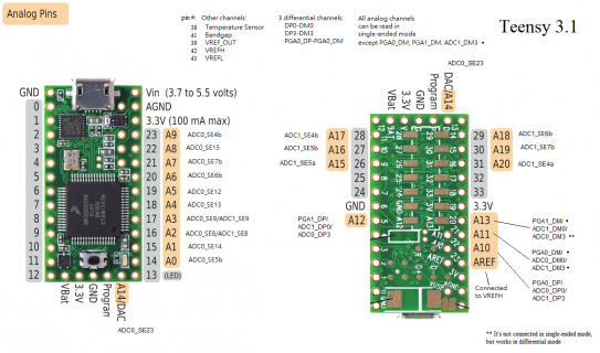
I saved this v3.1 Analog Pinout card (source?) that has more pixels and info with a focus on Analog. It shows alternate names as show in the K20 reference.

This may help here as well - I'm looking at this hoping to find a 16bit analog read pin so I can listen to sound with INMP401 a 1,000 times a second more or less to detect events - may end up doing FFT to see frequencies and not just peaks if I need to.

Hopefully I've interpreted these pins right and these are 16bits on the Teensy Hardware [the square braces are my reading of the attached image]?
K20 Chip pins 6.6.1 ADC electrical specifications
The 16-bit accuracy specifications listed in Table 24 and Table 25 are achievable on the differential pins ADCx_DP0 [ADC0_DP0==Pin22==A10], ADCx_DM0 [ADC1_DM0==Pin20==A13].

Teensy3_1_AnalogCard.png
 
Last edited:
I checked the clamping diodes an unfortunately(?) there is no positive clamping diode on digital pins. So you should add this yourself.
https://www.pjrc.com/teensy/K20P64M72SF1.pdf, pg. 11
1. All 5 V tolerant digital I/O pins are internally clamped to Vss through a ESD protection diode. There is no diode connection to Vdd.
Also the function to calculate the resistor value is given. Note that this resistor value is for a dc voltage. The limitation will be dissipation. Since a piezo will give spikes, the value of either 1k (Paul) or 10k (me) will be more than sufficient. I did not calculate the datasheet value yet.
 
Just basically the first image of post #5
Code:
                         +--- 3V3
                         |
                        --
                        /\  diode
                         |
  +-----+----+--+---Rs---+--- Input
  |     |    |  |
piezo zener  C  Rp
  |     |    |  |
  +-----+----+--+----------- GND
The C is always good as a bandwidth limitation
f-3db = 1/(2*pi*R*C), where R = 500, so C o.o.m. 10n
Rs = 1k...10k
Rp is to define the potential at the input, either >> 500. Or use a smaller value in case you need attenuation

instead of the secon diode, you could also put a second zener between input and gnd
Edit: Oops, sorry no protection in off state disregard this remark
 
Last edited:
I'm looking at this hoping to find a 16bit analog read pin so I can listen to sound with INMP401 a 1,000 times a second more or less to detect events - may end up doing FFT to see frequencies and not just peaks if I need to.
Hopefully I've interpreted these pins right and these are 16bits on the Teensy Hardware [the square braces are my reading of the attached image]?
What the datasheet claims and what the chip delivers are not always the same thing :). Paul has always been careful to claim only 13 bits of ADC resolution for Teensy 3/3.1. My old measurements of Teensy 3.0 ADC resolution in single-ended mode are here: http://dangerousprototypes.com/forum/viewtopic.php?f=2&t=4606
 
Actually if you read the datasheet carefully, a minimum SFDR of 78 dB is specified. Assuming SFDR is approximately SINAD, the effective number of bits is 12.7. So Pauls claim is in fact exactly what is stated in the datasheet.
 
Good Info, Thanks. 12.7 will be good - but if 16 were sitting there no sense in picking the wrong pin.

read the datasheet carefully
I thought I was doing good to find that in the 67 page manual - also glad for the msg#9 linked image associating the names with pins - those quoted notes and SFDR don't even show in search of the 1377 page RM. Thanks for decoding the 'Min. 78 dB' in that 'table 25' (Typ. is 90 dB) as 12.7 bits. For differential mode if I put ground on one pin and signal on the other would that push me to Min. 82 dB and Typ. is 95 dB? I have the pins to use - and my Analog Mic device will be mounted on/near the Teensy. This doesn't help the OP with 20 inputs and 21 analog pins and a longer run to a drum set.

I've read many of the web pjrc.com notes looking to find v3.1 info - they are so blended across versions with most exceptions and details focused on the v3.0 or before that some v3.1 details are not apparent when they are the same or better.

This where were I got the Analog pinout detail - and more to read on the thread for ADC library details.https://forum.pjrc.com/threads/25532-ADC-library-update-now-with-support-for-Teensy-3-1
 
Last edited:
The improved dynamic range of the differential mode comes from the fact that most spurious due eg. crosstalk and ground bounce is common mode. Futhermore it helps to suppress even order intermodulation products. By grounding one pin you destroy this improvement.
If you have to. At least connect your source ground pin also to the ground of the differential input and not just to some ground anywhere. Preferably with the 'differential ground' connected to the 0V by a resistor with the same resistance as the source impedance.

Edit: When I read this back it is some what fague.
The idea is to run one ground wire from the teensy 0V to your source -. Then run a wire from the + of your source back to the teensy ADC+. Also run another ground wire from the - of your source to the ADC- of the teensy. Preferably this last wire should have a resistor equal to the source impedance in series, placed close at the source -. Keep at least the wires connected to the ADC+ and - close together. From a low frequency perspective the two 'ground' wires (the ones connected to 0V and ADC-) seem to have the same voltage, but due to all kinds of parasitic coupling effects this is not the case. (FYI. I design circuits up to 120 GHz for my day job).

Oops should have read better
my Analog Mic device will be mounted on/near the Teensy
 
Last edited:
Good call - I was forgetting the pins are "VCC/GND/AUD" - it is a single ended output. The Sparkfun breakout seems to implement the need support hardware. Again just wanted to have the best pin I could since I have my pick - there is a 24bit I2S version just days in the future from @onehorse.
 
Last edited:
Status
Not open for further replies.
Back
Top