Ra8875 7" lcd

Status
Not open for further replies.

scoobydoo

Member
I have a 7” Chinese LCD board from buydisplay.com RA8875
I’ve tried to make it work on my Teensy 3.1, but after two day’s of trying,
I’m desperate, What I did:

4-Wire SPI:

Short: J1, J2, J3, J4, J5, J10, J12, J14, J16, J17 ( J8 now 5 volt)

Open: J6, J7, J9, J11, J13, J15

Resistors:

R1, R2, R3 = 10Kohm (There were already 10Kohm)
R35, R36, R37, R38 = 0ohm
R39, R40, R41, R42 = NC

40 pins board connector
5 ) SCS > teensy 10(cs)
6 ) SDO > teensy 11 (mosi)
7 ) SDI > teensy 12 (miso)
8 ) SCLK > teensy 13 (clk)
10 ) INT > teensy 20
11 ) RESET > teensy 21

I also connect all VSS & VDD pins and use
a separate power supply 5 amp.

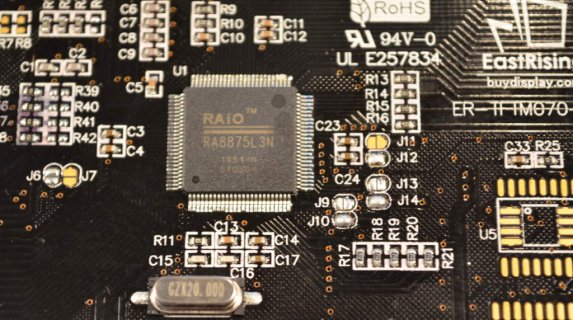
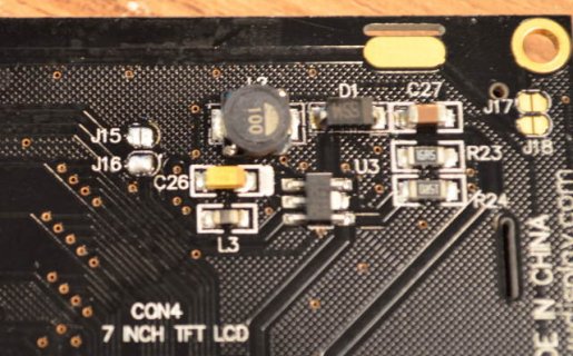
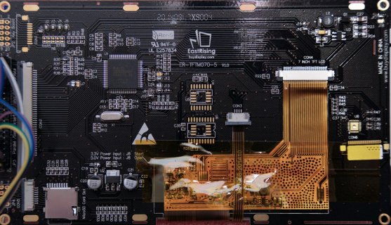
I made a picture from the backside of my board to show the configuration.
See below

I tried the following libraries:

  • Adafruit RA8875 Library:
    sumotoy/RA8875 on GitHub

I only get “RA8875 Not Found!”

Can anyone please help me ?
Code:
#include <SPI.h>
//#include <RA8875.h>
#include "Adafruit_GFX.h"
#include "Adafruit_RA8875.h"
 
#define RA8875_INT 20
#define RA8875_CS 10
#define RA8875_RESET 21
 
Adafruit_RA8875 tft = Adafruit_RA8875(RA8875_CS,RA8875_RESET);//Teensy

void setup() 
{
  Serial.begin(9600);
  while(!Serial){}

  Serial.println("RA8875 start");
  
  if (!tft.begin(RA8875_800x480)) {
    Serial.println("RA8875 Not Found!");
    while (1);
  }

board1.jpg
 
Last edited:
Maybe this conversation can help?

https://forum.pjrc.com/threads/2625...ler-with-Teensy3?p=61535&viewfull=1#post61535

It's mostly about the capacitive touch controller on some of those buydisplay products, but there's info in that conversation about how those particular types of displays need to be wired up.

Also, beware the known MISO tri-state problem on the RA8875 chip.

https://forum.pjrc.com/threads/24668-Teensy-3-*-Text-rendering-issue-with-RA8875-TFT-display/page2

You can NOT use any other SPI chips together with the RA8875, unless you add a tri-state buffer. The RA8875 does not disable its MISO pin like it should, so it will interfere with any other chip also connected to MISO (pin 12, DIN on Teensy 3.1).

More info about the SPI MISO problems can be found here:

http://www.dorkbotpdx.org/blog/paul/better_spi_bus_design_in_3_steps
 
When you do get it wired up properly, any change you could post a quick photo showing the correct connections. I'm sure it'll help anyone else who gets one of these not-so-well-documented Chinese displays and needs to figure out the wiring.
 
Hi Paul, thank you for helping me,
I have read all the links, but nothing works,
I turned over the MISO and MOSI wires and now tft.begin works sometimes,
when I compile and upload to my Arduino UNO, once in a while
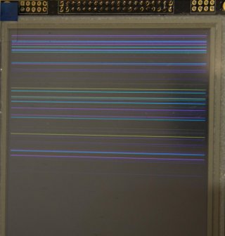
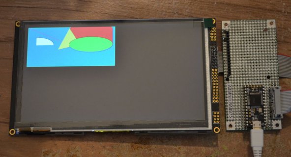
the backlight turns on, and I get stripes on the LCD.(picture).
but most of the time the backlight stays off.

I changed the teensy for an UNO to see if that works.
I only use one LCD on SPI and nothing else.

The tri-state solution, do you think It will help for one connected SPI device too.
I ordered an 74HC125 so I can try.

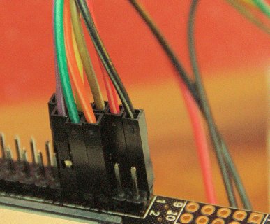
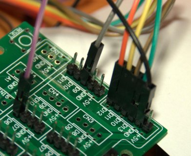
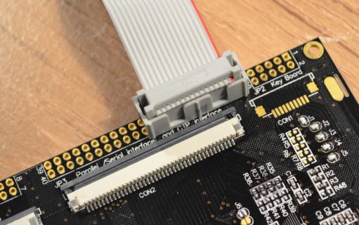
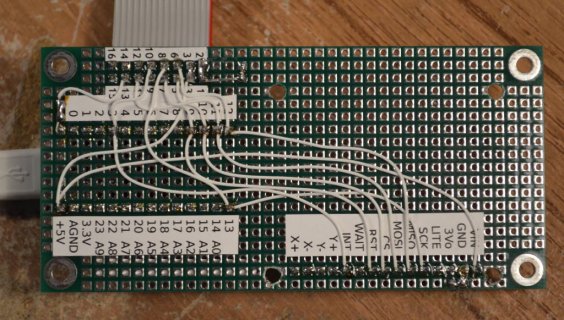
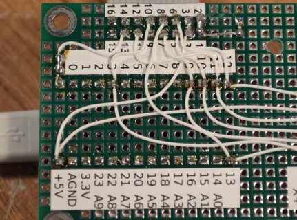
pictures:
D8 = purple
D9 = grey
D10 = brown

Thank you
boardcon.jpgstripes.jpguno.jpg
 
Oh, I didn't think of that !, perhaps I should try this first,
at first I thought it would be my fault for sure.
I will came back later after I contact buydisplay.com,
thank you Paul.
 
I've contacted buydisplay.com but they are not interested to help,
I have to look at the PDF files on there site, but I have done that already.
After checking my board and connections many times, maybe I must conclude
they have send me a broken LCD. Don't know what to anymore...
I've anyone has other ideas, please let me know.
 
ER-TFTM070-5
2014091
XS004

After a more compelling email, they asked for a picture of the LCD,
so they can see if it's broken. If it is I get a refund...
 
Just to pick up on a question a couple of posts back, you won't need to use a tristate chip if all you are using is a Uno/Teensy and the display. What I would ask is what voltage is the thing supposed to run at, since you say you used a 5V Uno and are about to swap in a 3.3V Teensy3.

The data sheet I found says 5V VDD and 3V logic, which means when you had the Uno driving the display it would have seen voltages well above spec, possibly causing the random lines/failure of the unit. This may not be the data sheet for your display but mismatching drive voltages certainly will not help things so suggest checking.
 
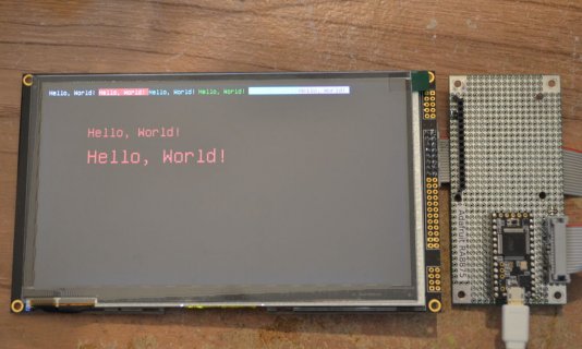
I have some very good news for you. I just happened to have exactly that same display here (buydisplay.com ER-TFTM070-5), just waiting to be someday tested with Teensy.

I connected it just now and it works great.

Here's the connections I used:

Code:
Teensy   ER-TFTM070-5
------   ------------
 GND          1
 GND          2
 VIN          3
 VIN          4
  3          10
  9          11
 10           5
 11           7
 12           6
 13           8
GND          13

I tested with Arduino 1.6.0 and Teensyduino 1.21-beta6. I used the Adafruit_RA8875 library which the Teensyduino installer adds.
 
I ran the 2 non-touch examples, builttest and textmode. The only change I made was editing the code to change RA8875_480x272 to RA8875_800x480 in tft.begin(). Otherwise, this was exactly the Adafruit_RA8875 library that Teensyduino 1.21-beta6 installs.
 
If you compare our connections, you've got pin 6 on the display wired to pin 11 on Teensy, and pin 7 on the display to pin 12 on Teensy. That's backwards. You definitely need to swap those wires!

If you use my connections from msg #11, it should magically work with the Adafruit example without any changes, other than configuring for the higher resolution.
 
GremlinWrangler, Thanks for your answer, yes on the shield it says 5 volt, but there is a level conversion underneath it (3.3 volt).

Paul, Thank you very much for all the work you did, I did follow everything you provide, but no luck, tomorrow I will look further,
It's almost morning in the Netherlands now...I'm very sleepy.
 
Fyod: At first I swapped miso/mosi I know, but after correcting this, still nothing happens...
The LCD is initialized, backlight goes on (sometimes) and then nothing more.

After Paul's perfect explanation (thank you Paul) I must come to the conclusion that I have to return the LCD,
Thank you all, I will come back in a few weeks to update this thread.
 
Hi Paul,
I have the same display from long time now, I've build up a library for that since I was not happy with the Adafruit solution.http://https://github.com/sumotoy/RA8875

Since months of testing I can say I know this display quite well, in my library I've used SPI transaction since they fit perfectly with this display, infact RA8875 support max 6.7Mhz in write and 3.3Mhz in read (looks strange but true and depends of the choosed xtal) so I can always work at the max supported speed.
In particular, the TFTM070 doesn not need the rst pin since it has his reset circuit in the design, I have to leave disconnected or it doesnt turn on.
But recently I had some big headache when I've tried to connect TFTM070,Audio board and SD holder working in the alternative SPI as should be if audio board it's in use. Of course I've used the 74hc125 on RA8875 MISO but it doesn't solve completely problems since display works but SD always fails! After hours of testing I find that disconnecting SCLK from display cause the SD works properly, I don't know if it's another RA8875 bug or TFTM070 bug but this the fact since I can replicate the same thing in another TFTM070 display.
So I've tried another 74hc125 port in the SCLK pin of the display to buffer it and isolate from SD card and...magically works. https://github.com/sumotoy/RA8875/wiki/Fix-compatibility-with-other-SPI-devices

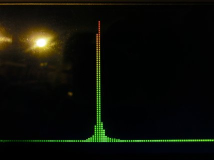
I can post in a couple of days a video of a real-time spectrum analyzer and simple audio player that shows 239 bands of 60 segments fully colored and really fast thanks to the layer capabilities of RA8875 (a really powerful feature ignored in the Adafruit library), there's a lot of demos in the library included gauges and vu bars created by using layer feature. https://github.com/sumotoy/RA8875/w...with-PJRC-Audio-Board-with-SD-card-and-RA8875
I will try tomorrow with Teensy LC, should work since RA8875 doen't need extreme speed SPI and since this chip has hardware graphics,internal RAM, Font chip, it's possible use a 128 Flash SPI (only if you program it first!), touchscreen and support a matrix keyboard as well it's perfect for nice interactive graphic interface without consume all MCU resources.
Before I forget, layers will works only for display equal or less that 640x480.
CIMG1886.JPG

Scoobydoo,
TFTM070 display have to be prepared to use SPI (some jumper on the back and needs 3 resistors on standard display), this is needed only if you ordered the standard version. On the Buydisplay site you can order already prepared for SPI but in one case I've received an half prepared one that doesn't have the 3 needed resistors so I had to add myself.
If you need help with configuration look this wiki https://github.com/sumotoy/RA8875/w...ydisplay-SPI-configuration-and-connections...

UPDATE:
I've improved library a lot and get really into RA8875 reagisters, thanks Christopher that gived me the idea I'm able to break the 10Mhz SPI and rised to 14Mhz, over it's possible but RA8875 doesn't work realiable.
It's safe now use the RST pin, the Eastrising 5" has an internal reset circuit but with a trick in code you can safely use it's reset pin.
The Adafruit library uses SPI mode 0 but in RA8875 datasheet it's clearly specified to use mode 3, also many functions needs SPI reading feedback that was missed on Adafruit (so why Paul added delay).
 
Last edited:
sumotoy
Thanks for your answer, I removed the resistors and caps, checked the jumpers, and Wow it works now,
but after turning the external power off/on it didn't work anymore,
I loaded an other sketch with the Adafruit library and there it was again: working,
after that I tried your library again the sketch works again,
after powering it down again, my Teensy is dead.
I ordered a new Teensy 3.1 but now I'm afraid to use the LCD again.
What could be wrong ? Any idea ?
 
Scooby doo you may need to add a delay before initializing the TFT, so it has time to startup internally and be ready for the SPI commands from the Teensy (which initializes very fast)
 
Hello,
very strange, I have the 2 Eastrising 5" and 7" here and both works perfectly.
Did you using the last version of the library? You are overclocking over 96Mhz ?
Display you are using?

PS
when you switch between libraries you need to do a complete power off since the reset of RA8875 doesn't clear all chip registers (another RA8875 bug)
And BE SURE to use the very last version of the library!
For continue this discussion please open an issue at https://github.com/sumotoy/RA8875, I always help everyone but I don't want to use board space for not officially (yet) supported library
 
Last edited:
Hey guys,
I've come back to tinkering with this LCD and I downloaded the sumotoy's newest library.
I get a few errors, not sure why. One of them is:

Code:
'class RA8875' has no member named 'roundGaugeTicker'
 
Reistalled IDE and TeensyD and all is well ;)
So much awesome work on this library Sumo, mad props to you!
 
I have a resistive touch version of the 5" display and I can't seem to get it to light up? It appears to work, but there is no light. I have connected a 1A 3V3 supply to the power pins on JP1 and the SPI connection is correctly setup.

Does anyone here have advice on how to make iturn on the backlight? cc @sumotoy
 
It was a long time ago when I was trying to make it work,
but I think I had to solder one of the jumpers on the backside of the TFT.
 
Status
Not open for further replies.
Back
Top