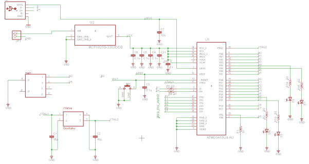
Hello, I’ve recently programmed the Teeny 2.0 dev board with success and now I have built my own custom PCB and am wanted to program to it. I am using the ATMega32u4 chips with the preprogrammed Halfkay Bootloader from PJRC.
The problem is, when I plug in the USB and connect to the custom PCB, the bootloader program does not detect it.
Things I’ve tried:
1. Checked all connections from the USB to the Microcontroller.
a. The D- line shows 0V, regardless of RESET button state.
b. The D+ line shows 3.3V when RESET is not pressed and 0V when RESET is pressed.
c. Note: The Teensy Dev. Board has a D+ and D- pin that have a periodic data stream when RESET not pressed and 0V when RESET is pressed.
2. Checked all connections from the Microcontroller to VCC and GND.
3. Checked the connections to the RESET button (Connected to GND when pressed, 3V when not pressed)
4. Checked all connections to the 16MHz Crystal Oscillator
a. Note: My Crystal Oscillator only shows 16MHz when the RESET button is pressed. This is different compared to the Teensy 2.0 Dev. Board. The
Teensy 2.0 Dev. Board shows the crystal oscillator oscillating at 16MHz regardless of RESET state.
I am are sort of at a point where we can’t think of anything else to try and so anything helps. Thanks.
Schematic:


