sumotoy...there are a lot of comments in the basic example of your RA8875 library, BUT you should mention that it doesn't draw anything at all. I almost had a heart attack when I uploaded it and nothing happened. The basic text example does show text, though - cool! Thank you for that lib.
You are using an out of date browser. It may not display this or other websites correctly.
You should upgrade or use an alternative browser.
You should upgrade or use an alternative browser.
the infamous RA8875 (again!) pullups on every SPI pins
- Thread starter sumotoy
- Start date
sumotoy
Well-known member
Oh, you mean register 0x88 and 0x89? Ouch, can be interesting, you opened a closed door! I have some spare time later so I can try something.
The datasheet (at the end) says that max SPI possible it's 20Mhz. Setting RA8875_PLLC1 = 0x05 and RA8875_PLLC2 = 0x00 will give sysClock to 30Mhz (20MHz * (5+1)) / ((1+1) * 2) = 30Mhz.
Now I can play with PLLDIVN (that should be 1..31). With 31 will give a SysClock: 20MHz * (31+1)) / ((1+1) * 2 = 160Mhz, so /3 = around 50Mhz, but max SPI speed supported by chip it's 20Mhz, need to change PLLDIVN with another division (sigh!).
So PLLDIVN = 11 -> SysClock: 20MHz * (11+1)) / ((1+1) * 2 = 60Mhz, divided by 3 give 20Mhz, this should be fine(?)
In conclusion:
RA8875_PLLC1 = 0x0C
RA8875_PLLC2 = 0x00
and set MAXSPISPEED to 20000000
I didn't try this, just fast calculations.
if you want to play with it check void RA8875::initialize(uint8_t initIndex) function:
then in RA8875.h file
Btw another bell ring my ears, the pullup resistors on all SPI lines can be a sign of SPI_MODE3 instead of SPI_MODE0? Can't wait to try it.
Even in SPI_MODE3 there's no reason for pullup resistors and useless condensers, cannot understand why the guy at Eastrising put them, if someone have a good explaination I will really appreciate.
And...yes, the eastrising (and other) cards controls the backlight from the RA pwm so power it without configuration result in a black screen with vertical lines in background.
About test, yes, you right , sorry for the earth attack
PS
If my fried RA8875 card will resume from dead of course...
The datasheet (at the end) says that max SPI possible it's 20Mhz. Setting RA8875_PLLC1 = 0x05 and RA8875_PLLC2 = 0x00 will give sysClock to 30Mhz (20MHz * (5+1)) / ((1+1) * 2) = 30Mhz.
Now I can play with PLLDIVN (that should be 1..31). With 31 will give a SysClock: 20MHz * (31+1)) / ((1+1) * 2 = 160Mhz, so /3 = around 50Mhz, but max SPI speed supported by chip it's 20Mhz, need to change PLLDIVN with another division (sigh!).
So PLLDIVN = 11 -> SysClock: 20MHz * (11+1)) / ((1+1) * 2 = 60Mhz, divided by 3 give 20Mhz, this should be fine(?)
In conclusion:
RA8875_PLLC1 = 0x0C
RA8875_PLLC2 = 0x00
and set MAXSPISPEED to 20000000
I didn't try this, just fast calculations.
if you want to play with it check void RA8875::initialize(uint8_t initIndex) function:
Code:
    writeReg(RA8875_PLLC1,initStrings[initIndex][0]);////PLL Control Register 1
    delay(1);
    writeReg(RA8875_PLLC2,initStrings[initIndex][1]);////PLL Control Register 2
    delay(1);

   //and maybe...

    writeReg(RA8875_PCSR,initStrings[initIndex][2]);//Pixel Clock Setting Register
    delay(1);
then in RA8875.h file
Code:
#if defined(__MK20DX128__) || defined(__MK20DX256__) //teensy 3, 3.1 (30Mhz max)
    #define MAXSPISPEED             6600000//3300000 in READ
#elif defined(__MKL26Z64__)                             //teensy LC     (12 or 24 Mhz max)
    #define MAXSPISPEED             6600000//3300000 in READ
#elif defined(__SAM3X8E__)                             // due
    #define MAXSPISPEED             6600000
#else                                                 //rest of the world
    #define MAXSPISPEED             4000000//2000000 in READ
#endifEven in SPI_MODE3 there's no reason for pullup resistors and useless condensers, cannot understand why the guy at Eastrising put them, if someone have a good explaination I will really appreciate.
And...yes, the eastrising (and other) cards controls the backlight from the RA pwm so power it without configuration result in a black screen with vertical lines in background.
About test, yes, you right
PS
If my fried RA8875 card will resume from dead of course...
Last edited:
sumotoy
Well-known member
I've done some testings, looking datasheet seems this chip needs SPI_MODE3.
By default, my library initialize PLLC1 as 0A and PLLC2 as 02, the result should be a sysClock of 36,7Mhz that correspond to a SPI max of 12.2 Mhz. I have tried to go at 10Mhz instead of my previous limit of 6.6Mhz, it works but not 100% reliable.
So I tried to initialize PLLC1 as 10 that correspond to a 56,7Mhz SysClock, SPI max at 18.9Mhz! I cannot go over 10Mhz, seems work but after a cold start the display fail to initialize. Even with this settings the max SPI speed where everithing works almost 100% of the times it's 8Mhz.
I have upped a new version that uses SPI_MODE3 on github (https://github.com/sumotoy/RA8875/), I'm waiting your testings christoph, you are a genius on math!
Last edited:
Yes, the display seems to like mode 3. I wrote a simple board file for the driver stub that comes with ugfx. That's slower than your driver, but works nonetheless. There are also many more features I can implement in that driver model.
But before I do that, I'll try to speed up the system clock and get a faster SPI.
But before I do that, I'll try to speed up the system clock and get a faster SPI.
After initializing I changed the PLL settings like this (not exactly your API, but you'll get the idea):
This should result in f_sys = 20 MHz.
After that, these SPI settings worked even after cycling power:
16 MHz was good, 20 MHz was like 16 Mhz, and 24 MHz worked relibably as well and was faster than the 16 or 20 MHz setting. I'm not sure about the actual frequency on the real SCK line, though...
Code:
write_reg8(g, RA8875_PLLC1, 0b1011); gfxSleepMilliseconds(1);
write_reg8(g, RA8875_PLLC2, 0b010); gfxSleepMilliseconds(1);
write_reg8(g, RA8875_PCSR, 0x82);After that, these SPI settings worked even after cycling power:
Code:
SPISettings(24000000, MSBFIRST, SPI_MODE3);sumotoy
Well-known member
PLLC1 = 0b1011 = 11 = 0x0B ?
PLLC2 = 0b010 = 2 = 0x02 ?
Maybe I'm wrong but should be 40Mhz sysClock so the teorical max SPI speed should be sysClock/3, around 13.4Mhz.
sysClock = (20MHz * (11+1)) / ((2+1) * 2) = 40.000.000
I have tried:
PLLC1 = 0x15
PLLC2 = 0x02
This give sysClock of around 73.4Mhz that result in a max SPI speed of 24.47Mhz
I have tried this last parameters but not satisfaction. Then I got an idea, dropped all initialization sequence at 8Mhz then rise up to 24Mhz (even on 15/20 cm cables on a breadboard) and worked!
The SPI Transaction of Paul really useful here!
Update:
I have used PLLC1 = 0x17, this give me 80Mhz -> 26.7Mhz max SPI speed. However the datasheet claim 20Mhz as the higher SPI frequency, my experiments shows 21Mhz as the highest possible reliable SPI speed, going over that result in garbage or wrong position addressing on mid/long periods.
Last edited:
PLLC1 = 0b1011 means PLLDIVM = 0, PLLDIVN = 11,
PLLC2 = 0b010 means PLLDIVK = 2.
the equation is: f_sys = f_in * (PLLDIVN + 1)/((PLLDIVM + 1) * (2^PLLDIVK))
with our values: f_sys = 20 MHz * 12 / (1*2^2) = 240 MHz / 4 = 60 MHz.
These values are actually the exact values from the example in the datasheet, chapter 6-8 "Clock and PLL" (if we happen to have the same revision). My initialization takes place at f_sys = 20 MHz (default values), f_SCK = 6 MHz, and when it is done I switch to f_sys = 60 MHz and f_SCK = 24 MHz.
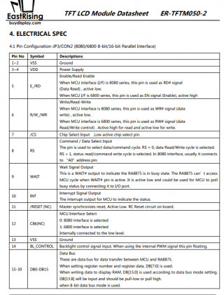
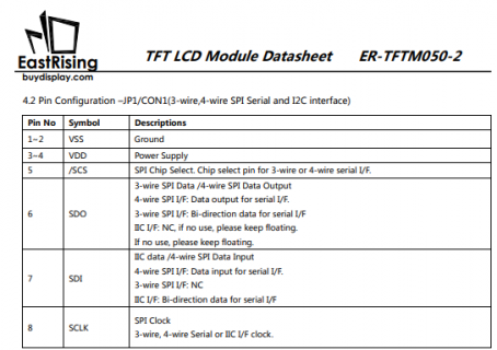
Is it possible that they put in R1..R3 for use with a parallel interface? If I used the parallel interface, I'd add pull-ups to all SPI inputs (SCK and MOSI at least) to give them a defined level. I ordered my display from ebay, and I didn't order a specific interface configuration.
I've got some more questions regarding this display, but they are not SPI related. I'm creating separate threads for those.
I've got some more questions regarding this display, but they are not SPI related. I'm creating separate threads for those.
sumotoy
Well-known member
Hello, christoph, looks like aI forget a 'power' in the formula! Anyway thanks to point me to this, opened again my interests to RA8875 and finally I solved the SD compatibility too..
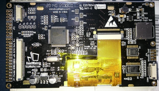
About resistors, it can be as you said, following datasheet there's a lot of pullup/pulldown in relation to the configuration choosed, but I just got a brand new Eastrising pre-configured for SPI and even this have the pullups, I think they leave as default. I've noticed that RA8875 have weaks I/O and using long cables cause any type of interferences so probably they added for minimize this. I just test the 2xRA8875 from Eastrising (272x480), exact the same but I have removed pullups and condensers to the older one, at 21Mhz SPI the new one has some screen garbage from time to time, the old it's perfect. Added an isolator circuit to both and connected an SD, the old one works, new one not and SD get stuck, same circuit. The Adafruit_RA8875 doesn't have any pullup resistors, it's SPI native.
About resistors, it can be as you said, following datasheet there's a lot of pullup/pulldown in relation to the configuration choosed, but I just got a brand new Eastrising pre-configured for SPI and even this have the pullups, I think they leave as default. I've noticed that RA8875 have weaks I/O and using long cables cause any type of interferences so probably they added for minimize this. I just test the 2xRA8875 from Eastrising (272x480), exact the same but I have removed pullups and condensers to the older one, at 21Mhz SPI the new one has some screen garbage from time to time, the old it's perfect. Added an isolator circuit to both and connected an SD, the old one works, new one not and SD get stuck, same circuit. The Adafruit_RA8875 doesn't have any pullup resistors, it's SPI native.
Last edited:
Hello,
This is the year 2023 and I am stuck with the same problem of the same display.
Bought "optimized" for 4 wire SPI. Connected CS-10, MOSI-11, MISO-12, SCK-13, GND and power 3.3V. The display acts as if it's dead. I tried multiple sketches, nothing works.
I wonder if someone has figured out how to make it work and there is a tutorial of some sort...Thank you!
KurtE
Senior Member+
Yes there are lots of us who have played with the RA8875 and have it working.
A better thread to look at is: https://forum.pjrc.com/threads/57280-RA8875-from-Buydisplay
Need a lot more details about your setup, in order to help much.
Things like:
a) What are you hooking it up to? A teensy? Which one?
b) What library are you using? Most of us are using the Fork/Branch: https://github.com/mjs513/RA8875/tree/RA8875_t4
I don't remember if this is the version that is now with Teensyduino?
c) What sketch are you using?
d) Which RA8875 display? One from BuyDisplay? Adafruit? Do you have a link to the one you purchased.
e) How do you have it hooked up? You mentioned 3.3v. However these displays can be power hungry and may likely require more amperage than the 3.3v output from a Teensy.
So the ones I ordered run on 5v and have their own 5v to 3.3v regulator.
f) How exactly is yours configured? For example some of the displays are setup with jumpers that require you to run an an IO pin to the backlight pin. Others are setup such that you must output a command to turn the backlight on.
Sorry not much to go on.
Thank you! I was able to make it work. The mistake was to plug the USB to the keyboard USB extension port. Plugging it directly to the computer solved the problem.
I wired the SPI using CS-10, MOSI-11, MISO-12, SCK-13. It looks like for the touchscreen I should use INT and RESET...? I cannot locate these pins on the display...
There is INT (10) and RESET (11) on JP3 (parallel port). Are these the correct ones?
I wired the SPI using CS-10, MOSI-11, MISO-12, SCK-13. It looks like for the touchscreen I should use INT and RESET...? I cannot locate these pins on the display...
There is INT (10) and RESET (11) on JP3 (parallel port). Are these the correct ones?
KurtE
Senior Member+
Sorry again hard to help here without knowing which display...Thank you! I was able to make it work. The mistake was to plug the USB to the keyboard USB extension port. Plugging it directly to the computer solved the problem.
I wired the SPI using CS-10, MOSI-11, MISO-12, SCK-13. It looks like for the touchscreen I should use INT and RESET...? I cannot locate these pins on the display...
There is INT (10) and RESET (11) on JP3 (parallel port). Are these the correct ones?
PaulStoffregen
Well-known member
A picture would be worth 1000 words here. Like literally, use your phone or a camera to take a photo, then post it in your message. Look for the "insert image" button in the tools right above the area you're typing your message.
We're able to help much more when we can actually see... especially if you choose a good camera angle so we can visually follow where the wires connect.
We're able to help much more when we can actually see... especially if you choose a good camera angle so we can visually follow where the wires connect.
PaulStoffregen
Well-known member
I'm confused, can't see any wires in your photo. How did you connect it to Teensy?
Paul, this is just a generic picture. I wired the SPI using CS-10, MOSI-11, MISO-12, SCK-13. It works great.
The question that I have is how to wire the touchscreen. My understanding I should use INT and RESET pins for the touchscreen. I found them on JP3 parallel port of the display. Are these the correct ones?


The question that I have is how to wire the touchscreen. My understanding I should use INT and RESET pins for the touchscreen. I found them on JP3 parallel port of the display. Are these the correct ones?


kd5rxt-mark
Well-known member
I wired the SPI using CS-10, MOSI-11, MISO-12, SCK-13. It works great.
The question that I have is how to wire the touchscreen. My understanding I should use INT and RESET pins for the touchscreen. I found them on JP3 parallel port of the display. Are these the correct ones?
This is how I wired the RA8875 in the latest version of my TeensyMIDIPolySynth:
Code:
// PIN D2       = RA8875 Touchscreen INT
// PIN D3       = RA8875 Touchscreen RESET
// PIN D26/A12  = RA8875 Touchscreen MOSI (MOSI1)
// PIN D27/A13  = RA8875 Touchscreen SCLK (SCK1)
// PIN D38/A14  = RA8875 Touchscreen CS (CS1)
// PIN D39/A15  = RA8875 Touchscreen MISO (MISO1)
Declarations:
Code:
// when used w/ Audio Adapter, must use an alternate CS pin for the display
const int RA8875_CHIP_SELECT     =  38;       // Teensy 38 (A14) -to- RA8875 05
const int RA8875_RESET           =   3;       // Teensy 03 (D03) -to -RA8875 11
const int RA8875_MISO            =  39;       // Teensy 39 (A15) -to- RA8875 06
const int RA8875_MOSI            =  26;       // Teensy 26 (A12) -to- RA8875 07
const int RA8875_SCLK            =  27;       // Teensy 27 (A13) -to- RA8875 08
const int RA8875_TS_INT          =   2;       // Teensy 02 (D02) -to- RA8875 33

const int RA8875_MAX_TOUCH_LIMIT =   1;

RA8875 tft = RA8875(RA8875_CHIP_SELECT, RA8875_RESET, RA8875_MOSI, RA8875_SCLK, RA8875_MISO);
Initialization:
Code:
   pinMode(RA8875_CHIP_SELECT, OUTPUT);
   digitalWrite(RA8875_CHIP_SELECT, HIGH);

   pinMode(RA8875_RESET, OUTPUT);
   digitalWrite(RA8875_RESET, LOW);

   check_time = millis();
   while ((millis() - check_time) <= 100);

   digitalWrite(RA8875_RESET, HIGH);

   tft.begin(RA8875_800x480);

   tft.DMA_enable();

   tft.setRotation(2);

   tft.clearScreen(RA8875_BLACK);

   tft.brightness(255);

   tft.useCapINT(RA8875_TS_INT);   // use the FT5206 chip interrupt

   tft.setTouchLimit(RA8875_MAX_TOUCH_LIMIT);

   tft.enableCapISR(true);         // capacitive touch screen interrupt it's armed

   tft.writeTo(L1);                // write to layer 1
Hope that helps . . .
Mark J Culross
KD5RXT
kd5rxt-mark
Well-known member
Thank you! I was referring to the physical wires that connect Teensy to the display. How do I wire the touch screen on the display side? Do I need to connect any other wires besides CS, MOSI, MISO, SCK, GND and power?
The pins that I listed above (see the "Declarations" section for actual pin numbers) includes all of the connections between the T4.1 & the RA8875 (of course, they also share +5VDC & GROUND). All connections at the RA8875 are made on the 40-pin connector.
Hope that helps . . .
Mark J Culross
KD5RXT
Note: this info is specifically for the CAPACITIVE touchscreen. If you have the RESISTIVE touchscreen instead, some of this will definitely be different. MJC
KurtE
Senior Member+
I am sorry for the confusion - this is exactly the same RA8875 display from East Rising you have discussed in this thread: 5" TFT LCD 800x480 w/ I2C serial SPI.
View attachment 31317
Actually in the different threads we have talked about several different versions of ones by BuyDisplay, some of us have also picked up some from Adafruit...
So 5" TFT LCD 800x480, I believe there have been a few different versions of the board. like: https://www.buydisplay.com/5-inch-tft-lcd-display-capacitive-touchscreen-ra8875-controller-800x480
This one comes with Capactive touch, some others had resistive touch, others none.
But assuming your display is the same as my last one...
One of the last sketches I have played around with this one as well as several others is a picture viewer... https://github.com/KurtE/mtp_tft_picture_view
Sorry no readme or anything...
But has sections in it like:
Code:
#if defined(RA8875_INT) && defined(USE_FT5206_TOUCH)
  tft.useCapINT(RA8875_INT);  //we use the capacitive chip Interrupt out!
  //the following set the max touches (max 5)
  //it can be placed inside loop but BEFORE touched()
  //to limit dinamically the touches (for example to 1)
  tft.setTouchLimit(MAXTOUCHLIMIT);
  tft.enableCapISR(true);  //capacitive touch screen interrupt it's armed
  Serial.println("** RA8875 FT5026 touch enabled **");
#else
  tft.print("you should open RA8875UserSettings.h file and uncomment USE_FT5206_TOUCH!");
#endif
I believe we don't need the FT5206 library as it may be built into the RA8875 library.
Sorry it has been awhile since I played much with these.
kd5rxt-mark
Well-known member
Whoops !! We may have two different displays. The info I provided is for interfacing to the 7" RA8875 display with the following characteristics:
Sorry if I caused any unnecessary confusion !!
Mark J Culross
KD5RXT
Code:
//    - controlled via buttons/sliders displayed on a 7" RA8875 800x480 display w/ touchscreen (rotation=2) from here:
//
//         https://www.buydisplay.com/7-inch-lcd-module-capacitive-touch-screen-panel-i2c-spi-serial
//
//         Display options (ER-TFTM070-5):
//            Interface:               Pin Header Connection-4-wire SPI
//            VDD:                     5.0V (can always change the jumper later to power from 3.3VDC)
//            Touch Panel:             7" Capacitive Touch Panel with Controller
//            MicroSD Card Interface:  Pin Header Connection (not useable - see display docs)
//            Font Chip:               (none selected)
//
//         Make sure to edit C:\Program Files (x86)\Arduino\hardware\teensy\avr\libraries\RA8875\_settings\RA8875UserSettings.h
//            - uncomment the following line: #define USE_FT5206_TOUCH//capacitive touch screen
Sorry if I caused any unnecessary confusion !!
Mark J Culross
KD5RXT


