How to read a I/O expander datasheet?

Status
Not open for further replies.

wolfv

Well-known member
I am trying to understand I/O expander datasheets.
Can you recommend a book or resource that explains I/O expanders and micro controllers so I can understand datasheets?

Take for example this one sentence from http://ww1.microchip.com/downloads/en/DeviceDoc/22103a.pdf 1.3.2.1 I2C Write Operation:
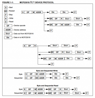
The I2C write operation includes the control byte and register address sequence, as shown in the bottom of Figure 1-1.
PCA9655E Figure 1-1.png
Nothing in Figure 1-1 is labeled "control byte" or "register address" and I don't know what they are.
I assume these are basic vocabulary because they are not defined in the datasheet.
Googling "I/O expander" "control byte" "register address sequence" only gets 8 results, all them datasheets.

Thank you.
 
"control byte" in the text and "device opcode" in the diagram appear to be two terms for the same thing. Similarly "register address" and "device address" seem to mean the same thing.

Think of the combination of opcode and address and meaning "do this". For a read operation, it means "get this specific data from this register". For write, it means "update this register with this data".

Does that help?
 
I can see your problem here with not having the vocab to ask google the right questions. Some places to start some random wandering:
http://en.wikipedia.org/wiki/Control_register
http://en.wikipedia.org/wiki/Processor_register
http://en.wikipedia.org/wiki/Opcode
http://en.wikipedia.org/wiki/Zilog_Z80

Checked stack overflow
http://stackoverflow.com/questions/10028104/reading-and-understanding-mcu-datasheet-and-codes
And it seems even that font of knowledge doesn't know of a resource focusing on data sheets for people coming at electronics sideways.
 
I consider this more an I2C, or better an issue of I2C implementation and this is not limited to I/O expander. In fact, most datasheets of devices that use I2C try to 'explain' their implementation, going sometimes into details that may only be needed if one implements the I2C protocol from scratch.
But after having inspected different I2C devices one quickly recognized the important information.
 
Reading datasheets always involves some interpretation and sometimes even a little guesswork, which you check by trying tests on the real chip.

The thing to understand is datasheets are imperfect. First of all, they're written by marketing people, not engineers. The datasheet's only purpose is to sell you the part. A big part of that is documenting features and performance. But never forget it really is a sales pitch. Often when a part has some limitation or poor spec, they'll just gloss over or even omit any mention of it.

Datasheets use all sorts of inconsistent language. Sometimes the terminology is words the have taken on a particular meaning at the company, on even within a specific group or project. Most well written datasheets will define terms somehow. But there aren't any rigid standards. Every company just makes up whatever they feel like writing. Always remember, the primary purpose is convincing you to design the part into your product.
 
Thank you for all your responses. All of them are informative.
Paul, you comment made me smile. I am glad you're the engineering type, and that Teensy controllers sell them selves.

After digesting the information the datasheet made more sense.
GremlinWrangler's links where very useful.
WMXZ's comment inspired me to read http://en.wikipedia.org/wiki/I²C

Using Nantonos definitions of "device opcode" and "device address", I made a guess as to how Arduino Wire works.
This Wire.write() example gets compiled with the Arduino library to write machine code:
Code:
	 Wire.beginTransmission(ADDR);
	  Wire.write(0x0C);		// GPPUA ADDR
	  Wire.write(0xFF);		// DIN..DIN
	 Wire.endTransmission();
When the machine code runs on Teensy, Teesny sends the following I2C messages to MCP23018 (notation from Figure 1-1):
S, OP, W, ADDR -> DIN...DIN -> P​
Is that right?

Also, what is a "Serial Interface block"? The MCP23018 datasheet says:
1.3 Serial Interface
This block handles the functionality of the I2C (MCP23018) or SPI (MCP23S18) interface protocol. The MCP23X18 contains twenty two (22) individual registers (eleven [11] register pairs) which can be addressed through the Serial Interface block (Table 1-1).
 
Last edited:
The "Serial Interface Block" is that part of the chip that interprets what happens on the I²C or SPI lines, like tracking the Start and Stop conditions, address and data bytes and such. There must be some logic that counts clock transitions and assembles single bits into bytes, and that is the "Serial Interface Block".

The Teensy also has such blocks, like the I²C, SPI or UART peripherals. That last sentence is also an example of the inconsistencies Paul mentioned - for a microcontroller, these are peripherals connected to the core, and for the MCP23018 they are just a "block", named as such by Microchip.
 
Status
Not open for further replies.
Back
Top