
Hello,
Introdution:
I am an eletrician with a little knowledge of electronics, english and with almost no knowledge of programming. So for me, this is a realy big big project!
What is this project:
This intend to be an ambient thermostat with 6 important objective:
1) It must have a graphic display;
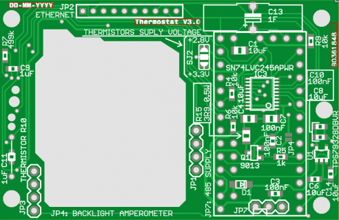
2) it must have a slave modbus RTU interface;
3) It must measure light intensity;
4) it must measure humidity;
5) it must measure (obviusly) the temperature;
6) it must be small enough to stay in a "wall box fo the light switch"
Why I need it:
1) It is cool!
2) my house will be domotic and the core is a Siemens s7 1200 PLC , Modbus RTU is the simple way to comunicate with.
3) two reasons: one is to let the plc know how many lux are in a room and choose to if turn the light on or off; the second for turn the TFT backlight off when not needed or when I sleep.
4) automatically power on the fan when needed (especially in the bathroom)
5) ...
6) I like it and non rwcessed screens are ugly.
Optionally can have an ethernet interface (future implementation) and a micro sd reader (just in case).
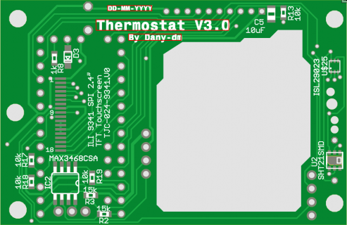
so far i've bought many tft screen and at last i've choose a ILI9341 2.4" SPI TFT with touchscreen that fit exactly on a 3 modules of "Vimar" plate.
http://www.ebay.com/itm/2-4-240x320-SPI-Serial-TFT-Color-LCD-Display-Module-ILI9341-Touch-Panel-Screen/311058563693?_trksid=p2047675.c100005.m1851&_trkparms=aid%3D222007%26algo%3DSIC.MBE%26ao%3D1%26asc%3D28774%26meid%3D11d058b44d0340a0b9ac9c52fb1b1eb8%26pid%3D100005%26rk%3D2%26rkt%3D6%26sd%3D400760404213&rt=nc
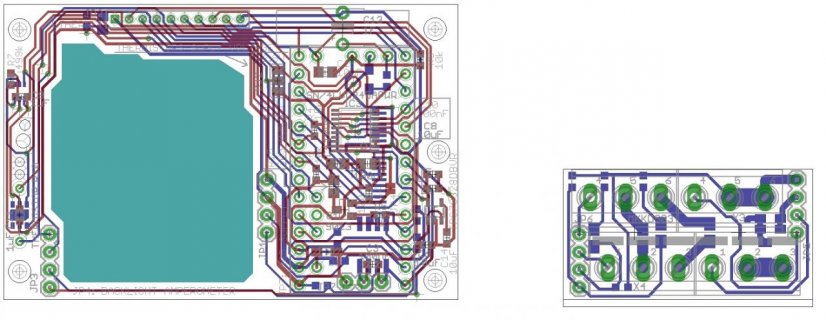
I've seen the GY-30 light sensor module but i prefer to integrate it into my pcb because i am very restricted in space. (max pcb dimensions L= 65.3mm (2.57") X h= 42.5mm (1.67")). In the schematics i've drawn ISL29023 as light sensor chip because i can easily find it on RS http://uk.rs-online.com/web/p/colour-light-sensors/7044546/ and for the same reasons i've choose the SHT21 (http://uk.rs-online.com/web/p/temperature-humidity-sensors/7865554/) as humidity and temperature sensor.
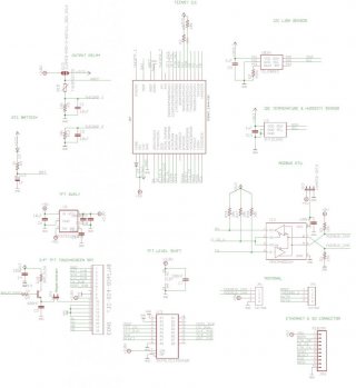
i've appended my pdf schematic, what do you think? are all components connected right?
Introdution:
I am an eletrician with a little knowledge of electronics, english and with almost no knowledge of programming. So for me, this is a realy big big project!
What is this project:
This intend to be an ambient thermostat with 6 important objective:
1) It must have a graphic display;
2) it must have a slave modbus RTU interface;
3) It must measure light intensity;
4) it must measure humidity;
5) it must measure (obviusly) the temperature;
6) it must be small enough to stay in a "wall box fo the light switch"
Why I need it:
1) It is cool!
2) my house will be domotic and the core is a Siemens s7 1200 PLC , Modbus RTU is the simple way to comunicate with.
3) two reasons: one is to let the plc know how many lux are in a room and choose to if turn the light on or off; the second for turn the TFT backlight off when not needed or when I sleep.
4) automatically power on the fan when needed (especially in the bathroom)
5) ...
6) I like it and non rwcessed screens are ugly.
Optionally can have an ethernet interface (future implementation) and a micro sd reader (just in case).
so far i've bought many tft screen and at last i've choose a ILI9341 2.4" SPI TFT with touchscreen that fit exactly on a 3 modules of "Vimar" plate.
http://www.ebay.com/itm/2-4-240x320-SPI-Serial-TFT-Color-LCD-Display-Module-ILI9341-Touch-Panel-Screen/311058563693?_trksid=p2047675.c100005.m1851&_trkparms=aid%3D222007%26algo%3DSIC.MBE%26ao%3D1%26asc%3D28774%26meid%3D11d058b44d0340a0b9ac9c52fb1b1eb8%26pid%3D100005%26rk%3D2%26rkt%3D6%26sd%3D400760404213&rt=nc
I've seen the GY-30 light sensor module but i prefer to integrate it into my pcb because i am very restricted in space. (max pcb dimensions L= 65.3mm (2.57") X h= 42.5mm (1.67")). In the schematics i've drawn ISL29023 as light sensor chip because i can easily find it on RS http://uk.rs-online.com/web/p/colour-light-sensors/7044546/ and for the same reasons i've choose the SHT21 (http://uk.rs-online.com/web/p/temperature-humidity-sensors/7865554/) as humidity and temperature sensor.
i've appended my pdf schematic, what do you think? are all components connected right?

")