Long SPI cables and 100 ohm resistors

Status
Not open for further replies.
Terminating resistor are important when lines get long in relation to the risetime of the signals.
Long lines have the problem, that the voltage is not instantaneously at the output. If the line is not terminated, the signal will travel up and down the line, distorting the signal. The best would be to terminate the line at both sides, but this requires line drivers and has the disadvantage of signal attenuation. A way around it is to singly terminate the line. This will still cause the wave to be reflected, but its energy is absorbed at the source again.
So yes in series with the cable. Make sure you place the resistor at the source side of the cable.

Edit: the source side is the teensy for all signals, except MISO, where it is the device.
 
Long - like inches or feet?
You can't be precise, but generally feet (e.g. > 0.4 m). In some cases, while 100 ohm is 'ideal', using a lower value (e.g. 47 ohm) will provide a signal with faster rise time at the other end. This makes it more likely to be received correctly.

The ideal value depends on the wiring construction -- e.g. if it a piece of ribbon cable, or just some 'random' wires.
 
The value of the series terminating resistor depends on a number of factors, such as the desired impedance on the line. Also the width of the wires, the distance of the microstrip to the GND plane, distance between wires if they're differential pairs, etc. When I still had multiple devices on the SPI bus, I calculated a 120 Ohm resistor as the closest thing to perfect. They probably were not needed in account of the short distance but it's a good idea to use them to stop reflections.
 
The lengths of the wires (I try to connect 9 devices) differ from about 10cm to about 65cm. I'll try with 100ohm, but am interested - let's say it still doesn't work: how would I check the influence of the resistors - would I have to use an oscilloscope? Might I have to use different resistor values for the different wires?

I now have a setup with 7 SPI-displays (with wire length as stated above) that works well by itself.

wiring_7_displays_2000x632.jpg

But: as soon as I connect another device (SD card, connected with ~18cm wires) to the teensy 3.1, the setup stops working.

I use a 74HC125 on the MISO lines (to tri-state the line) - do I only place a resistor near the MISO of each device/display or also one from the out-line of the 74HC125 going back to the teensy?
 
Last edited:
Terminating a the source only works well if you have a single line with a source at one end and a receiver at the other. If you have devices between the source and the end, those devices will see the reflections (from the end), and may not work well.

With loose wires like you have, the impedance is likely higher than 100 ohm -- so try higher resistance (200 ohm). This may slow down the edges and does make them sensitive to noise, but the Teensy has hysteresis on its inputs (its MISO), so it is somewhat immune. If your slave devices don't have hysteresis, it can cause trouble. Also, don't expect to run the SPI at the highest clock frequencies -- keep it reasonable (< 4 MHz or so).

Have you confirmed that the SPI mode { SPI.setDataMode(SPI_MODEx); } is consistent between your master and slaves ?

If your slave devices consume a lot of current (or change their current consumption very quickly), and you don't have adequate decoupling on them (0.1 - 10 uF on power to GND line), the transients this generates could also cause problems.

Is your setup 'star'-connected (e.g. individual sets of wires between master and each slave) ? or daisy-chained (e.g. long wires from master to the farthest slave) and the other ones tapped along the length ? If star, you'll have trouble with reflections from each slave back to the master (can you determine if your data errors are from master to slave, or the other way ?)
 
The beaviour of the setup at the moment is as follows:
When I unplug the SD card I can use all seven displays without problems.
When I unplug the displays from the wirenet, I can access the connected SD using SDFAT library without problems.
Connecing two or three displays and the SD card, I can access the SD card and talk to the displays.
Once I connect the SD card and more than two or three displays, I cannot talk to the SD card anymore (but to the displays).

I realize that I'll probably have to rebuild my wirenet ... At the moment, it's a daisy-chain where the connection to the master goes off in the middle of the daisy-chain (see picture below). Is it correct that you suggest a clean daisy-chain that is connected to the master at one end?
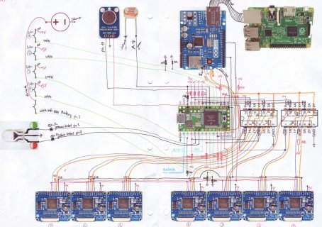
schema_2000x1411.jpg

BTW: At the moment, I replaced the ethernet shield by a solo SD card breakout board (the one by Paul).

And yes, the slaves do draw a lot of current (250mA per device), so I'll add the capacitors (where would I have to look on how to calculate the ideal capacity?).
At least, both the displays and the SD card run at MODE0 (and it is set accordingly).
I'll use 180 ohm resistors (which I have at home).

A lot of work, thanks for all your suggestions, I'll post more as soon as I'm done trying.
Dani
 
I can't (easily) decipher your schematic, so it is hard to be definitive. Here are some things I would think about (especially if you don't have an oscilloscope):

1) commonest SPI problems are the quality (rise/fall time, noise) on SCLK and CSB. If you are doing software CSB control, then you likely will have plenty of time delay between CSB falling and the 1st SCLK transition -- that's good.

2) SCLK glitches (noise, reflections) can cause problems -- this can be worse with more loads on the line (modules) -- if it works with (say) 3, but not 7, does it work with 3, and additional capacitance (10-30 pF ?) ? -- if you don't have a 'scope, this can help distinguish between reflections or just capacitive loading causing problems. If it is capacitive loading, perhaps you can just use additional HC125 buffers to drive subgroups of SCLK lines ?

3) Does it work when you only have small loads on the SPI peripherals (e.g. low LED current, small numbers of LEDs etc. ?) ? Can you confirm if the problems are sending or in receiving data ?

4) You could use 0.1 uF and 10 uF in parallel on the boards -- but the board may already have these.

5) Ensure your ground wire is as good as the SPI signal wires --this includes the GND to the buffers as well as to the peripherals. It might be best to 'star' connect these -- individual wires back to a single GND point on the SPI master. Connect the GND of the +5 V power supply to here also. I realize this amount of wire might be difficult, so maybe group them -- e.g. separate wires for all the left peripheral group, the right group, the HC125s etc.

6) I didn't search much, but it's better if the 3-state buffers have hysteresis -- maybe some versions do ? What about LS244 ?

7) try reduce the 5 V power supply to the buffers and the peripherals -- 4.5 V (If you don't have a variable one, a diode in series will work e.g. IN4001..7) may reduce noise enough to make progress and understand where the problems are coming from.
 
Great! I added some resistors (100 ohm, I had done it before I heard about the 200 ohms) to the MISO and the SCK pins (close to the source of the signal), reduced the clock frequency by factor 2 and now it works! THANK YOU VERY MUCH.

7_displays_im_dunkeln.jpg

7_displays_im_hellen.jpg
Since I have already soldered so much - I'll stick to my setup for the moment and go into thorough funtional testing. If it keeps working (next step is to add the ethernet shield (which is known to cause trouble)), I won't change my wirenet, even if it's a little slower than it could theoretically be. I'll keep you posted.
Dani
 
Last edited:
Beware that "working" is a fuzzy term in this context. What you'll see with compromised waveform correctness due to long/capacitive cables is a bit error rate increase. Errors won't show up in a brief test.

Most ARM vendors' SPI controller have an option for CRC checking to detect (but not correct) bit errors. This came from SD cards where the odds of a bit error are significant in high volumes of data at high speeds.

So always run the SPI clock as low as you can given the application.
 
Actually, below some threshold (which is the point where the clock signal ultimately can settle at the rail levels), there is no advantage to further reducing the clock rate.

There are 2 aspects to the wire termination that can cause problems. With ringing (unterminated) lines, signals can reflect, and you can get multiple transitions at each node. in a worse case, ringing can take a long time to dame out. With over damped lines (e.g. too much R; additional C on the line), the rise and fall times are extended. This limits the max rate signals can change on the lines, and also makes the lines sensitive to noise (if the receiver doesn't have hysteresis). For example, if the signals rise and fall with 10 ns rates, then noise would have to happen in this window to cause corruption; but of the rise/fall times are 1 us, then there is a larger window of opportunity for problems.

Be aware that CSB can be nearly as critical as the clock signal -- bounce on this can cause spurious CSB events (which would tend to look like 0-bit SPI transfers). Some periphals will ignore those, others will do strange things.

Generally, MISO and MOSI are not sensitive to problems because these signals are level sensitive -- as long as the signal is at the 'right' level at the SCLK edge, what it did before this doesn't matter.
 
Status
Not open for further replies.
Back
Top