Interleaved PWM signals

Status
Not open for further replies.

someteen

Well-known member
I need to generate two PWM signals using Teensy 3.1. The timmings look like that:
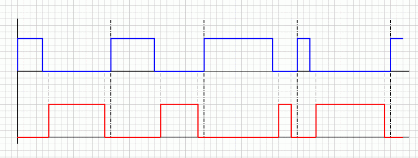
wave.gif

Actually, the two PWM signals are complementary but there is a deadtime (2us) between rise and fall of each waveform (I need to drive a MOSFET half-bridge so I have to avoid the shoot-through/cross-conduction by using that deadtime).

In my current implementation, I'm using a timebase of 2us (one cell width, in the image above) and I'm using digitalWrite to set the output pins accordingly.

Anyway, that's a very time (CPU) consuming task (triggering a 2us interrupt continuously). Is there a way to generate those signals using hardware timers?
 
The Flex Timer Module FTM on the Teensy 3 should be able to generate complementary PWM signals with inserted deadtime. True, I havnt tried it, but if it works then the hardware will do the heavy lifting for you and the 2us timer interrups will not be needed.
 
Sorry, this is just from the K20 Sub-Family Reference Manual, I suppose this is not in the libraries, and needs a bit of
playing around with low level hardware. If you search the forum for FTM , interleaved PWM you will get a bit more info.

Still an idea is better than none :)

Edit: I might work this out if I have a long sunday afternoon free
 
Last edited:
You would figure they would have some basic how to guide on doing something like that, most other chip manufacturers that have multiphase motor specific hardware bother to at least give examples and explanations on using them.
 
I start work now, couple of minutes at my desk before I have to slog it running our SMD Line for the day (because our usual op quit on us).

following whollender's link I found http://cache.freescale.com/files/microcontrollers/doc/app_note/AN4560.pdf?fasp=1

@someteen please read through that and see if you can find what you need, I can look at it much more thoroughly than the skim I just gave it a moment ago in about 8~9 hours - maybe by then, if you haven't happened to figure it out, you will have a lead for me you can post about in the mean time.
 
Thanks everyone for your suggestions. Seems like a CTC timer is the best approach. I found lots of examples for AVR (updating the OCR1A compare register with variable values) but that's not going to work on Teensy (as far as I read).

Anyway, I'll try to use cascading IntervalTimers to do the job.

I'm going to use three timers: a main timer (100us), a dead timer (2us) and a duty timer (variable: 10-90us). I need dead timer and duty timer to act like a monostable pulse (one shot only). So the timmings should look like that:

Code:
tmrMain()
{
    tmrDead.begin();
    ..
}

tmrDead()
{
    tmrDead.end();
    tmrDuty.begin();
    ..
}

tmrDuty()
{
    tmrDuty.end();
    tmrDead.begin();
    ..
}

Is that OK to put a timer.end() statement inside the actual subroutine triggered by that timer? I guess the subroutine still runs but it wont be triggered again (till the next timer.begin() statement). Am I wrong?
 
have you seen this thread @someteen https://forum.pjrc.com/threads/25044-Teensy-3-1-PWM-for-BLDC ?

I think you may benefit most by reading the majority of posts in it but posts #8 & #17 should give you a reasonable start, if you do want to have a bash at doing it with hardware - if you give it your best shot and don't quite nail it then you can always post what you've got and ask (politely) if anyone can fix it :)


What you've made there doesn't look like a good way to organise software PWM.

Two tips: (1) no floating point and consider keeping variables down to 16 bits at most.

(2) One ISR does the whole job based on counters

You need 4 comparison values indicating on and off times per channel in the counter sequence, or could use 3 comparison values where 2 are center of dead time on & off and 1 is dead time, perhaps half of the dead time offset.
 
Thanks a lot, @robsoles!

It looks like the right implementation, indeed. Anyway, I have to modify it to suit my needs as I'm not driving a BLDC motor but a MOSFET full-bridge (H-bridge) using unipolar sine modulated PWM signals.

If I'll get lost, I will kin.. I mean, politely(!) ask you for support.

Many thanks to @Barney, too!

(2) One ISR does the whole job based on counters

You need 4 comparison values indicating on and off times per channel in the counter sequence, or could use 3 comparison values where 2 are center of dead time on & off and 1 is dead time, perhaps half of the dead time offset.

Actually, that's how I made it at first, but that ISR was running every 2us (deadtime duration), so I could switch the digital outputs high/low before and after the deadtime).
 
Hi Someteen
I had exactly the same issue last year. AFAICR this is trivially simple on a Arduino, not so with a Teensy.
It's often called 'phase correct' pwm
I was building a class D amplifier which has the same requirements.
Someone on here provided a solution. I MIGHT still have the code if you've not sorted it.
Cheers

Ian
 
Someteen
I found it - I can't promise that this works...

Code:
/*
Phase correct PWM using Teensy 3.x flex timer
 */

const int ledPin =  13;
const int PWM_H = 9;     //  FTM0 - CH2
const int PWM_L = 10;    //  FTM0 - CH3

#define TPM_C 48000000            // core clock, for calculation only - [bus clock? IS]
#define PWM_FREQ 93750            //  PWM frequency [Hz] - 93750 gives 9bit pwm (?) or is it 10?
// something not quite right here measured f is 47kHz & resolution is 10 bit
// sorted need TPM_C = 48MHz above [IS]
#define MODULO (TPM_C / PWM_FREQ) // calculation the modulo for FTM0

int PWMvalue;

void setup()   {                
  pinMode(ledPin, OUTPUT);
  init_FTM0();
  Serial.begin(115200);      //debug
}

void loop()                     
{

  PWMvalue=analogRead(A8)>>1;      //analogue in
  FTM0_C3V = PWMvalue;         //10 - 9 bit
  FTM0_SYNC |= 0x80;             // set PWM value update

  digitalWrite(ledPin,!digitalRead(ledPin));  //toggle led
  delay(100);  //debug
  Serial.print("Modulo : ");
  Serial.println(MODULO);    //debug
  Serial.print("PWMvalue : ");
  Serial.println(PWMvalue);
}

void init_FTM0(){

  FTM0_POL = 0;                  // Positive Polarity 
  FTM0_OUTMASK = 0xFF;           // Use mask to disable outputs
  FTM0_SC = 0x08;                // set system clock as source for FTM0
  FTM0_MOD = MODULO;             // Period register
  FTM0_CNTIN = 0;                // Counter initial value
  FTM0_COMBINE = 0x00003300;     // COMBINE=1, COMP=1, DTEN=1, SYNCEN=1
  FTM0_MODE = 0x01;              // Enable FTM0
  FTM0_SYNC = 0x02;              // PWM sync @ max loading point enable
  FTM0_DEADTIME = 0x80;          // DeadTimer prescale systemClk/4
  FTM0_DEADTIME |= 0x3;           // 1uS DeadTime, max of 63 counts of 48Mhz clock ***[was 0xC] changed - IS***
  FTM0_C2V = 0;                  // Combine mode, pulse-width controlled by...
  FTM0_C3V = MODULO/2;           //   odd channel.
  FTM0_SYNC |= 0x80;             // set PWM value update
  FTM0_C2SC = 0x28;              // PWM output, edge aligned, positive signal
  FTM0_C3SC = 0x28;              // PWM output, edge aligned, positive signal

  CORE_PIN9_CONFIG = PORT_PCR_MUX(4) | PORT_PCR_DSE | PORT_PCR_SRE;    //config teensy output port pins
  CORE_PIN10_CONFIG = PORT_PCR_MUX(4) | PORT_PCR_DSE | PORT_PCR_SRE;   //config teensy output port pins

  FTM0_OUTMASK = 0x0;            // Turns on PWM output

  /*  To update the PWM duty cycle, 
   write MODULO value to the FTM0_CnV of the odd combined channels.
   then use "FTM0_SYNC |= 0x80" to set the software trigger.
   */
}

Cheers

Ian
 
Last edited:
Many thanks, Ian! I've just ran your code and it actually worked quite well.

However, in the meantime, I've decided to only generate a single PWM signal and feed it to a simple hardware board (logic gates) to generate the complementary signal with the inserted deadtimes.

By generating both signals using the MCU there is the posibility (in case of accidental freeze/lockup/reset) that the analog outputs would have unpredictable states (or just high impedance) hence all the MOSFETs could be driven ON at the same time (and that's the definition of disaster).
I'm using a bunch of costly MOSFETs and I want to protect them as much as I could.

Beside, the PWM frequency and the deadtime durations are constant for my applications so I prefer to play safe.

Anyway, your code it's a must-have library. Congratulations for your hard work (the class D amplifier)!
 
If you are designing a custom hardware board and have logic left over it may be worth adding some sort of E-Stop that triggers if for any reason FETs are enabled for >1PWM cycle. Have seen this to track the case where a FET actually goes short circuit and you want to protect the downstream components from a steady DC application. This is probably overkill for what you are doing, but having a something with a crow bar protection system is always fun

http://en.wikipedia.org/wiki/Crowbar_(circuit)

Some systems actually had a physical bar that dropped into the power rails in an attempt to save the downstream components. A fairly spectacular protective device.
 
Thanks for the tip, but that's more like an overvoltage protection. The cross-conduction will generate a shortcircuit, hence I need some kind of overcurrent protection.

Anyway, the "logic" needed to actually get two complementary signals with deadtime inserted from a single PWM signal it's a single cheap IC (hex schmitt-trigger inverters).
 
@GrimlinWrangler
The only uses for "Crowbars" where I work is to dissipate voltage on a Field(DC application) before changing directions.

@someteen
I have actually seen a case in which an MCU froze while we where running lights in a Y configuration because of noise on a JTAG connection(stronger pull downs fixed it). The MCU stopped responding but the PWM hardware remained on pulsing the last set of 3 phase duty cycle and position data that had been given.

@post 16
That sounds like a simple and effective way to do it for a none changing frequency. I will warn you that starting a motor using a "line start" where you start at the desired frequency without a ramp up will require around 10 times the rated operating current for however long is required to get the motor to speed.

Generally the over-current protection I see at work is a mix of software for OC limiting and using opamps and comparators to set a hard limit that will cause a fault.
 
That sounds like a simple and effective way to do it for a none changing frequency. I will warn you that starting a motor using a "line start" where you start at the desired frequency without a ramp up will require around 10 times the rated operating current for however long is required to get the motor to speed.


I'm also using a startup procedure to avoid the inrush current. I'm starting at 90 degree ("full wave") but with a lower amplitude. Then, during next few cycles, everything reach the normal operation parameters.

Btw, I'm not driving a motor. I'm just building a sine wave inverter.

Generally the over-current protection I see at work is a mix of software for OC limiting and using opamps and comparators to set a hard limit that will cause a fault.

I also have a current sensor on the DC link connected to my Teensy but, in case of freeze/lockup I can't count on it either. That's why I have to put a second protection beside the existing fuse (though recently a MOSFET "saved" my fuse).
 
Status
Not open for further replies.
Back
Top