Verification of Input Protection Circuit

Status
Not open for further replies.
Hi Guys,

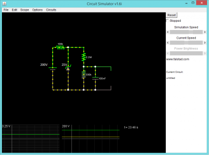
I need to read automotive voltage using a Teensy. I need good accuracy between 10 and 20V and have set up the voltage divider such that the full range of 0-3.3V corresponds with 0-25V to provide some buffer for the zener errors. I just want to verify that the following looks good; my simulations seem to indicate the limiting factors will be the power dissipation of the 100K resistor and the zener diode. Thoughts?

Circuit.png
 
I would use lower value resistors, at least 10X less, probably even 100X lower.

Zener diodes have terrible leakage current. At higher temperature, it can be on the scale of 1 uA. Using a 100K series resistor before the zener is asking for significant measurement error if the zener conducts, and changes its leakage of the wide range of temperatures you'd expect in a car.

Likewise, high impedances are noise prone. The 100 nF capacitor will help, but if the engine is running, a 300K DC source impedance isn't going to work so well.

Of course lower impedance will allow the terrible voltage spikes (especially if the car's battery is disconnected while the engine runs) to couple more strongly to the Teensy. But a 1K resistor to a zener will help limit then pretty well, and 22K series impedance and the smoothing effect of low-pass filtering with the capacitor should be plenty to protect the Teensy. It can actually handle about 10 mA of injected current, which would correspond to over 200V on the zener with the 22K resistor, even without the capacitor.
 
If you're running circuit simulations, try looking for a zener model that simulates temperature dependent leakage current. You might also try adding simulation for the ADC in Teensy, which looks mostly like a 1K resistor, 5 pF capacitor to ground, and a switch to another approx 20 pF of capacitance, and another switch that causes the 20pF to start in fully discharged state when the other switch connects it to the input. You really want the voltage to not be impacted much by that switch opening and closing.

Even that is very approximate and based on quite a bit of guesswork. The really tough thing about analog circuit simulation is it's hard to figure out how to really model real systems. Generally, you get that type of intuition from the oppose of simulators, mainly by painful experience of building and troubleshooting real physical circuits.
 
I had wondered about the large impedance. I started with a 1k but got worried about too much power through the 1K resistor. I will use something that can handle reasonable surge currents. As I only need to output the average voltage over a second or so I will just use a good zener and hope leakage does not affect the results to much. Thanks a lot for your help!
 
Last edited:
If you're looking for a ready solution, there are dedicated ICs for exactly this purpose. If you're looking to learn how to design your own input protection circuits from discrete components, you might still find the data sheets for these components interesting.

Disclaimer: The links above are from a quick Google search. I have no idea if the particular part I referred to is good/cheap/available.
 
Automotive transients get to about 50 V for a duration of about 100 ms. You should size your zener and the 1st resistor for that.
1: Small zeners can handle about 400 mW continuously, about 1 W for this small duration -- at 25 V, that's 40 mA. With 50 V at the input and 25 V on the zener, that's (50-25)/R = 40 mA ==> R = 625 ohms -- so use 1 kohm. With 1 kohm, zener leakage (few uA) will have a negligible effect.

2: Now you want to divide the input so 25 V generates 3.3 V. That's a ratio of 3.3/25 = 0.132 -- let's use 1/8 for simplicity.

3: Remember you still have 1 k in the input path (and the zener has no effect for 'normal' voltages). To divide by 8, you need 7*R on the top and 1*R on the bottom, but the 7*R should include the value of the 1 k. A good starting point for the lower R is 1 k. This means the upper one is 7 k total, or 6 k allowing for the first 1k. You can't (easily) get 6 k resistors, but 2 12 k's in parallel will work.

So, now you have: 1 k from the battery to the zener; the zener to ground, 12k//12k from the zener to the ADC input, and 1k from that node to GND. Add a 100 nF also, and you have a reasonable circuit.

Check power dissipation:
At 50 V, the current is 25 mA (from (50-25)V/1k); so the power is I^2*R = 0.025^2*1000 = 0.62 W. This is only for a transient, the static power would be (assume 16 V max. if you have a bad battery; 26 V if you get jump starts from 24 V trucks !) across 1k+6k+1k, or 8k. This power is V^2/R = 16^2/8k = 32 mW -- no problem for the components.

Accuracy -- Resistors may be about 2 % tolerance -- so this will limit your circuit's accuracy. They will be reasonably stable, so you could calibrate and include the cal in your software. A larger error may be how you connect to the voltage you want to measure -- 'Ground' is not easily defined in an automotive system, and vehicle chassis may be 100's of mV different from the battery -ve terminal due do battery and lighting currents (as well as starter currents etc.).
 
GeoffCubed, first and foremost, since you’re going to be reading voltage from an automotive sensor, please know that the power supply going to the sensor and the controller circuit has to be made free of noise, that is, the AC ripple which will appear because you’ll be getting power supply from an alternator. Secondly, you’ll need a small buffer along with that voltage divider. You can also use an inverting amplifier and set the gain accordingly.

pcba manufacturing
 
Last edited:
Status
Not open for further replies.
Back
Top