cantgetnosleep
Member
Hello,
I'd greatly appreciate any suggestions if someone's willing to take a moment.
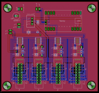
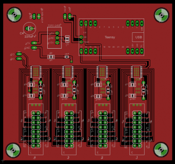
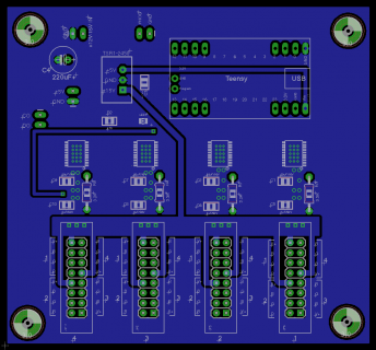
I'm making a breakout board for the TLC59711 with 4 of them plus a Teensy 3.1 as a microcontroller. I've created the schematic and pcb in Eagle (attached), and I'd appreciate a more experienced eye on them. Find any errors? Any suggestions on board layout? The idea is to use the TLC59711s as LED controllers. (I realize there are other ways to control LEDs that are easier but for this project I need to perform very smooth, low level fades, and because of this I need the 16-bit resolution to avoid stair-stepping the lowest light levels.)
Thanks,
Andrew
PCB both layers:

PCB top layer:

PCB bottom layer:

I'd greatly appreciate any suggestions if someone's willing to take a moment.
I'm making a breakout board for the TLC59711 with 4 of them plus a Teensy 3.1 as a microcontroller. I've created the schematic and pcb in Eagle (attached), and I'd appreciate a more experienced eye on them. Find any errors? Any suggestions on board layout? The idea is to use the TLC59711s as LED controllers. (I realize there are other ways to control LEDs that are easier but for this project I need to perform very smooth, low level fades, and because of this I need the 16-bit resolution to avoid stair-stepping the lowest light levels.)
Thanks,
Andrew
PCB both layers:

PCB top layer:

PCB bottom layer:


