WizFi250?

Status
Not open for further replies.
Not sure if the OP is intrigued by the ESP8266 instead of WixFi250 but the ESP8266 shows lots of movement in the last month - On chip Arduino support as well as full function WiFi with IOT services. Link to Digistump_Erik's OAK project in the works longer than that - hopefully a robust complete solution with good support. Not sure how much of the OAK is doable with ian's design - i.e. what the larger module brings?

Another Blog ... guy getting samples and working with the completed boards too through the growing pains: http://tech.scargill.net/category/esp8266/. Initial boot reset to load code and first xxxIO dev dropped off and another XxxxIO dev tree came out looking better.

Led to other links - PWM notes at the time show it as software powered and dropping when the net gets busy, IDE support at 1.6.2 with 50MB add-on package. And suggested SPI and i2c (master so far) were to be bitbanged at the time - not sure how that will work out but that seems like a job for a LC/3.1 co-processor, I assume OAK has some solution to those as his card shows the pin assignments for them - more to see on that in the next week.

Having a separate Net_WiFi (co)processor to handle that and web (with timeouts and 50% of its cycles burned on networking) not freezing a Teensy - nor counting on it for real time continuity sounds promising - ala onehorse. The Serial hardware and (256B) buffers on the ESP8266 should at least match the Teensy so speed over direct wire might keep that from bogging down Serial coming and going.

onehorse - will you expose the antenna beyond the Teensy? If so the ESP analog or other unique pin(s) 'out there' with a blinky might be a handy supplement - if not as @small.
 
will you expose the antenna beyond the Teensy

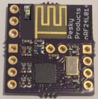
Yes, and this is somewhat of a concern. I am currently thinking of having the antenna inside the Teensy footprint to keep the total device length from growing and also to keep the USB port clear of obstruction. I'll have to see what kind of signal reception is possible with this arrangement. I want to keep the entire board less that 0.5 sq. in. including antenna. This is doable with the nRF24L01+, so should be doable with the ESP8266. I'll start on the design in a week or so and post here with what the first iteration of the board looks like...

I am waiting to get access to the esp8266 forum so i can get more detailed documentation. Building a board based on the reference design is easy. Getting the board to do anything requires some understanding of how the firmware works, which I have none at the moment. I'll likely need a lot of help, and I can only hope that the ESP8266 forum might be half as useful as the Teensy forum has been for me!
 
Holding it under the Teensy - the depth of a pin spacer - would clear most USB cables - if the cable is there already you aren't saving any length going smaller at the cost of range/interference - though the cable won't help either. Even a Rt Angle USB plug adds .56-.75" and your nRF24 is near .4" exposed and is .56 sq in. For the added function I think .56 or .63 would be a safe goal.

Moving the silk screen P.P. Logo down over the radio mask and putting A0 and i2c and a LED out there you could get stand alone capability (with the other 8/10 pins)? You'd have a bread boardable unit with more than the 8 pins on a $4.50 Addicore ESP8266 - like in ian's two board solution.
pp_esp8266.png
With that (+power) you could have an @small nano i2c 9DOF radio tracker.
 
My only concern with mounting the board under the Teensy is the loss of reception. When I have a board assembled I will test this and see if it matters much.

I have worked to get the nRF24L01+ radio board down below 0.5 sq. inch, the latest iteration succeeds. No reason not to try with the ESP8266. Although I agree, I would like to breakout as much ESP8266 functionality as possible. I should easily get 6 pinouts plus RX/TX and maybe 8 plus RX/TX; that gets pretty close to fully functional. I don't think this kind of board intended as a Teensy add-on will satisfy those who are looking for a standalone unit and don't care about size, but there might be a happy middle ground.
 
Given ESP processor - it runs itself without a Teensy by design. Except for size compromise, any move in that direction can only add value for both uses. Shared pins beyond the first 4 will mostly just get in the way of other Teensy hardware as all you need to talk is the serial link. Looking at OAK pinout, do you need Enable, Reset, Wake?

For reference: The OAK has 18 pins - dropping 4 SPI - you'd have 12 or all 14 shared at 8 and 10 pins - with 3 (4 w/led ) outboard independently, @small at ~double$.

Anyhow - that is view - my wholly divorced from the actual effort and details. Either way it beats the nRF24, and I'll probably order two OAK's next week.

Battery?: OAL length with .4 out is about the same size as a 400mAh Lipo.

(edit) Antenna: You noted the board wire antenna is more omnidirectional than ceramic - under the Teensy could only compromise that.
 
Last edited:
You're right about the redundancy. That is why I will have a minimal board first try out. There is little need to exercise the ESP processor when it is strapped to the Teensy 3.1. Its only function is a wifi port.

I was thinking of having my cake and eating it too, by having the same board be stand alone and breadboardable. I might do this too, but it is unlikely the same board suitable for the limited Teensy application will be very useful for the general non-Teensy application.

One possibility is to break out 5 of the ESP GPIO pins along the bottom edge of the board for access while mounted on the Teensy. This won't take any valuable Teensy pins other than the 3V3, GND, RX/TX pins needed. It would be useful to add another SPI port to the Teensy 3.1. But it is rather kludgy.

I'll figure something out. Design is all about compromise and tradeoffs.
Thanks for helping me see this better.
 
Last edited:
Cool to hear I'm helping! Will be interesting to see how it turns out. The ESP on a low spec 8 bit AVR would be a huge help. On Teensy only as much as offloading the network details saves resources, hang free while providing the ESP (msg#6) Features.

Just signed into OSH - 50% more area is $7.50 .vs. $10? I'd wonder if any extra pins broken out might make sure you didn't end up with a brick and lose a month? Add a second outside header pin row for ISP or whatever that might mean. Can you breakout VIN/GND pads to solder a USB plug on the bottom?

Teensy / Breadboard / Stand Alone : would be good cake to have and eat. What is the standard IOT use - just a couple data points from 5-10 distant spots? Unless it is a WiFi 3D printer - much home/work I/O is scattered. If the S.A. unit has 4-7 I/O could you 'monitor' a local area? If you want more or a central 'server' - bolt on an LC or 3.1. Of course reading that and looking at <$12 OAK would be cost effective.

Edit> Just saw this $10 adapter in Tindie email: FemtoCow/esp8266-ftdi-and-breadboard-adapter-with-33v-reg
 
Last edited:
On the cheap esp8266 boards, there is a extra flash chip. It's a bit slow, with a faster one (i.e. the winbond w128..) the esp can be clocked higher and is a bit faster.
The esp8266 on these boards contains a bootloader which receives serial data and writes them to the external flash.

The "official" firmware allows "unlimited" baudrates, i tried up to 2.5 MBaud and it worked. The max transfer-rate is ~600..800 kBPS (receiving).
But if you could provide spi on your board instead of the uart this would be great. But in this case some changes to the firmware are needed (don't ask me..:) don't know how to do this..
 
Last edited:
extra flash chip

I plan on using this SPI flash chip which looks to be pretty fast.

It seems to be straightforward to breakout the SPI pins from the ESP8266, but I am not sure at the moment how to enable the SPI function though. I have a lot to learn about this device, but it has the potential to significantly augment the Teensy 3.1 and eventually we will learn how to make the best use of it.
 
I saw a note on OC'ing to double speed, onehorse will do that (flash) right. More speed - more heat more often?

Heat note: ESP8266 can take as much as 300mA, that could mean 0.5W dissipation @5V input. The amount of heat cannot be overlooked. This Adapter looks handy if huge.

250+kBPS over serial seems better than tying up SPI. Wouldn't UART hardware buffering make serial less disruptive (on both sides)? Teensy multi device SPI already takes effort/care, and watching the LC come online with lesser SPI hardware makes serial look better, especially if the ESP SPI needs mods or results in bitbanging.
 
Last edited:
I would think that the radio uses up to 300mA only when transmitting a frame. A frame is a couple of mSec, and even with a constant 802.11 transfer, the transmitter duty cycle is likely less that 50%. But that's still a lot of current for WiFi.
I've seen some 8051 based ethernet devices use 150-200 mA or so. Due to the old core technology.
 
I don't think the thermal load is going to be the biggest problem with this device...

... would be nice if it were - except for the Teensy close proximity - at least you can add heat sink - but not use the antenna I suppose.

You are adding your own power - another thread user was faced with 100mA not able to power the ESP8266 on direct connect - the same is the published case on nRF24 with ext antenna. That was interesting because I hadn't seen that the 3.3v supply on Teensy is the MCU - I wondered why it was that low.

onehorse: when powered by your LiPo unit would that battery supply current over and above that from the MCU or is it still distributed across the Teensy only from the MCU?
 
The ESP8266 module will get its power from the same source as the Teensy. via LiPo battery connected to VIN. Separate regulators (one on the ESP8266 board and one already on the Teensy) will take care of distributing and stepping down the voltage to the respective devices. The regulator I chose will allow 300 mA continuous current to the ESP8266 and maybe a bit more for short intervals. Should be plenty. I like the regulator because it is 1 mm x 1 mm and doesn't even need passives with a battery source!
 
onehorse - not sure I asked a valid question - or the one I intended. Your board is indeed self supplied from 5v as needed, the Teensy couldn't do it. I was wondering if the Teensy is supplied with a good 3.3v - like from your battery board - does that replace the on chip current limited supply - for use on the Teeny board itself.

Also: The mentioned OAK hardware - based on ESP8266EX - and is now on KickStarter for Sept delivery at $10. At 1" square it is HUGE by onehorse standards - but looks interesting in what it incorporates/promises.
 
The Teensy has a pretty good 3V3 regulated supply limited to 25 mA per pin and 100 mA total power out even when supplied by LiPo through VIN. Good enough to source power for a lot of sensor boards via digitalWrite(HIGH) for 3V3, which I find very convenient even though the Teensy 3.1 has three separate 3V3/GND spigots on board; very generously endowed.

I had to resubmit the NDA to Espressif but my ESP8266 chips just arrived so I will have to get to designing the first board.

I am way behind on my projects: I am working on a new battery charger layout (very difficult in a 0.3 x 0.7 inch footprint), and I have all the parts for an Origin Nano Hornet (4 mm x 4 mm) GPS add-on board, several different motor controller boards including stepper motor controller, and a nice decorative wearable owl with eyes continuously running through the colors of the rainbow (for little girls and daring men!). Made a package error on the last and had to redesign it. Ugh!
 
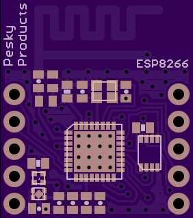
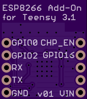
Finally got some time to start a simple design of an add-on board with the ESP8266. The first cut has been submitted to OSH Park. I am not totally satisfied with the design having had to make several compromises, but it is good enough to at least prove the concept. Here is a link if anyone wants to inspect the result.

i.png i.png
 
This is not compatible with Audioboard, but with some trickery (wires instead of pins) perhaps possible.. :)confused:)
I buy one :)
 
Last edited:
Hi Frank, This is not intended to work with the audio board. it is the first iteration of wht I hope will be a more useful set of boards that enable wifi on the Teensy for various purposes. I like this format since it mounts on the USB end of the Teensy where the battery charger also goes and leaves the front (non-USB) end free for all the sensors I would hang off the Teensy. I would like to be able to get telemtry directly to the laptop without having two radio modules.

Once I get this concept to work and gain some (good) experience with the ESP8266 I would consider designing a board with 1) the same footprint as the Teensy with 2) lots of SPI memory and 3) this ESP8266 for wifi. This kind of board would likely be useful to those who would like to record and stream audio. Maybe this is what you have in mind?
 
Yes, I have wlan audiostreaming working in private project and would like to make it "nicer" without so much wires (i'll post a picture later..)
If you have wlan-audio-streaming in mind, please think of adding 256 KB SPI-RAM (minimum, i'm still not sure because i wait for the delivery of additional chips.. :) ) for buffering packets, in a later version.

And the possibility to connect the ili9341 would be fantastic :)

Edit:
The T3.1 CPU-Usage is only 25%-40% (including mp3 with fft256 and 20Bargraphs) when streaming.
 
Last edited:
I just realized that it is be a very good idea to have GPIO13 & GPIO15 available - these are RTS/CTS for Hardwarehandshake.
I just ordered another ESP8266 Board.

In the meantime, I try to patch the original "AT-Software", perhaps it is possible to use GPIO0&2 as workaround with a bit trickery in the AT-software?
If it works ( I'm not sure ) , I will publish a patch for the most used "ESP-01" Boards

Frank.
 
Status
Not open for further replies.
Back
Top