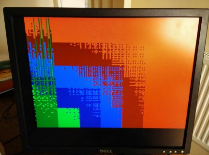
simple working VGA output with Teensy3.1

Status
Not open for further replies.

mortonkopf

Well-known member
Hi all, I am working on a project, for which a 'by product' was getting a solid VGA RGB output from Teensy 3.1. I managed to get something up and running by using the work done by Lukas Hartmann, and greatly simplified his code to be left with the bare bones of getting a signal up and running:
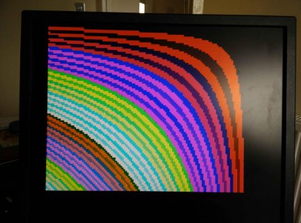
VGA_output_Teensy31.jpg

As you can see, its a simple set up and the code below only outputs from an array filled in the loop. It is 120 by 100 pixels, with padding on the timings to produce a reasonable graphic spread. I really should be looking at buffer filling from SD files and possibly using DMA, but at the moment that isn't my priority. Hopefully someone will find it useful for their projects.

The code uses port manipulation on port B to get the pins changing quickly enough, with resistors on the outputs to produce the 0.7v signal required for the VGA monitor. I tried a range of values, and it seems like the 270 to 470 ohm area was good. The timings are critical, and the image is easily lost with even minor changes, hence the availability of some NOP for padding.

mortonkopf

EDIT: please see corrected code in later post - A pointer is needed to recall the correct buffer values!

Code:
//based on timings from Lukas Hartmann
//https://www.youtube.com/watch?v=FfxH6zlsDGo
// using 72MHz Teensy 3.1
// using resistors on outputs to derive 0.7v signals

#define Width  120 //sreen pixels
#define Height  100  //screen pixels

uint8_t lcdBuffer[Height*Width]; 

// VGA PINS
#define RGB_OUT GPIOB_PDOR
#define PIN_VR1 16 
#define PIN_VR2 17
#define PIN_VG1 19
#define PIN_VG2 18
#define PIN_VB1 0
#define PIN_VB2 1
#define PIN_VI1 32
#define PIN_VI2 25
#define PIN_VBLANK 8
#define PIN_HBLANK 7


static volatile int VSYNC = 0;

#define NOP asm volatile("nop\n\t");

volatile uint32_t currentLine = 0;
volatile uint32_t currentFrame = 0;

IntervalTimer timer0;

#define UPPER_BORDER 40

void timerLine() {
  cli();

  if (currentLine>1) {
    digitalWrite(PIN_VBLANK, 1);
  } else {
    digitalWrite(PIN_VBLANK, 0);
  }

  digitalWrite(PIN_HBLANK, 0);
  RGB_OUT = 0x00;
  RGB_OUT = 0x00;
  RGB_OUT = 0x00;
  RGB_OUT = 0x00;
  
  digitalWrite(PIN_HBLANK, 1);

  currentLine++;
  currentLine = currentLine%525;

  NOP;

  uint32_t y = (currentLine - UPPER_BORDER)>>2;//how many rows to duplicate (to square up the image)

//display output section is within the timer >>
  if (y>=0 && y<Height){  //for each row do
  
    for (int i=0; i<40; i++) {//left edge buffer
      RGB_OUT = 0;
    }

      for (int x=Width; x>0; x--) {
      uint32_t color = lcdBuffer[x*y];

      color = color | (color<<12); //shift bits
      RGB_OUT = color;
      RGB_OUT = color;
      RGB_OUT = color;
      RGB_OUT = color; //four calls wide to square up each pixel
    }//end of one row of pixels
  }//end of display output section

  VSYNC = 0;
   if (y==80) {  
    VSYNC = 1;
  }
//  RGB_OUT = 0;
  sei();
}


void setup()   {

  delay(500);
  pinMode(PIN_VR1, OUTPUT);
  pinMode(PIN_VG1, OUTPUT);
  pinMode(PIN_VB1, OUTPUT);
  pinMode(PIN_VI1, OUTPUT);
  pinMode(PIN_VR2, OUTPUT);
  pinMode(PIN_VG2, OUTPUT);
  pinMode(PIN_VB2, OUTPUT);
  pinMode(PIN_VI2, OUTPUT);
  pinMode(PIN_VBLANK, OUTPUT);
  pinMode(PIN_HBLANK, OUTPUT);
  
  timer0.begin(timerLine, 31.468);

}

unsigned int tick = 0;

int y =0;

void loop()          
{
    if (VSYNC==1) {
      tick++;   
      VSYNC=0;
      //fill the buffer
 for (y=20;y<1500;y++){
        for (int x=0;x<(Height*Width);x++){ //this just fills the buffer with some colours
          lcdBuffer[x] = x/y;
          }}
       for (y=1500;y>20;y--){
        for (int x=0;x<(Height*Width);x++){ //this just fills the buffer with some colours
          lcdBuffer[x] = x/y;
          }}    
          
////do some stuff here?////////
    }
}


The timings for the screen output are:
Vertical
60 Hz frame rate
1/60 = 0.016667 Seconds period (16667 uS)
525 vertical scan lines (480 visible)
Therefore: 1 / 60 / 525 = 31.746 uS per line (13.5 KHz)
Vertical sync pulse: 2 lines ( 64 uS)
Back porch: 33 lines ( 1047 uS)
Visible area: 480 lines (15238 uS)
Front porch: 10 lines ( 317 uS)
---------------------------------------
TOTAL 16666 uS per frame

Horizontal
31.746 uS per line (13.5 KHz)
800 pixels per line (640 visible)
Therefore: 1 / 60 / 525 / 800 = 39.68 nS per pixel (25.2 MHz)
Horizontal sync pulse: 96 pixels ( 3.81 uS)
Back porch: 48 pixels ( 1.90 uS)
Visible area: 640 pixels (25.40 uS)
Front porch: 16 pixels ( 0.63 uS)
-------------------------------------------
TOTAL 31.74 uS per line
 
Last edited:
Here is a video of the video output using a for loop to generate the maths for the buffer:

https://www.youtube.com/watch?v=1HPvmHNzgmI

will post code for 60fps graphic update shortly

EDIT: I have update the post above with the code to generate the video graphics from a buffer that has values changing for each screen update, so it produces 60fps moving graphics
 
Last edited:
That's some nice work chasing the beam there, and may actually be useful since I've been looking for a cost effective solution to produce 8 unique VGA test images and 8 Teensyies is rather more friendly than 8 anything else's.

Looking through the code this is producing 3 bit/8 colour, and during each scanline you actually have spare some spare cycles in the horizontal pixels. For given value of 'spare' of course when repeatable timing is critical. What is the purpose of the declarations for VG2,VB2 and VR2? Are they just the returns or have I misunderstood the spec, or are you getting clever with resistive dividers to actually get 2 bit colour depth?
 
@GremlinWrangler. Yep, you got it re pins VG2, VB2 and VR2. If you use different resistor values for these, you can increase the range of colours as the colour signal goes through a simple voltage divider process using the 75ohm internal resistor of the screen. Nick Gammon has some great VGA discussion around this http://www.gammon.com.au/forum/?id=11608, and I found a lot of help understanding the concept at http://www.xess.com/blog/vga-the-rest-of-the-story/

ranging the resistor values to give two options for each colour output gives a dull and bright value for each colour channel.

On timing, I used the spare clock ticks to square up the image. In the width setting loop there are four calls to the same value to make each 'pixel' wider on the screen, and on the row loop each row is output twice to make a nice visual representation. Given work on buffers / DMA, I guess that it would be possible to increase the pixel density and reduce the duplicated row and width output, but storage and pixel value updates from buffers are the issue with greater pixel resolution a the moment (-well, for my skill level anyhow).
 
You can use the two colour output pins to give these six basic colours:

VGA_Teensy3_1.jpg

here you see that each of red, blue and green have two output values, dull and bright. these can then go into the colour palette mix because we are using PORT manipulation to choose. So (for others reading this) we can send out colour voltages using:

PORTB = B00000001 for example, for Red bright, or PORTB = B00000010 for red dull.(this is an e.g., as have not checked right now which pin is which…)
As an example for colour manipulation, we can then use a ref array for the PORT pins using hex values to represent the binary port values.
byte colours[6] = {0x01,0x02,0x04,0x08,0x10,0x20};, which would equal the right ones and noughts to switch pins high or low.
So, it is using 6 bits of each byte, decimal 1,2,4,8,16,32, hex as above
 
Last edited:
The original code in post one was a first attempt. I realised that the buffer addresses needed to use a pointer in order to remove incorrect recalling of colour values. Here is the updated code using a pointer (it also has individual pixel address, line, and screen fill) - again, this is all the work of Lukas:

Video of corrected output: https://www.youtube.com/watch?v=Jy4_sMtPBqg

Code:
//based on timings from Lukas Hartmann
//also added the drawing functions from Lukas.
//https://www.youtube.com/watch?v=FfxH6zlsDGo
// using 72MHz Teensy 3.1
// using resistors on outputs to derive 0.7v signals

#define Width  120 //sreen pixels
#define Height  100  //screen pixels

uint8_t lcdBuffer[Height*Width]; 

// VGA PINS
#define RGB_OUT GPIOB_PDOR
#define PIN_VR1 16 
#define PIN_VR2 17
#define PIN_VG1 19
#define PIN_VG2 18
#define PIN_VB1 0
#define PIN_VB2 1
//#define PIN_VI1 32 //not used in this code - can delete
//#define PIN_VI2 25 //not used in this code - can delete
#define PIN_VBLANK 8
#define PIN_HBLANK 7

byte colours[6] = {0x01,0x02,0x04,0x08,0x10,0x20};

static volatile int VSYNC = 0;

#define NOP asm volatile("nop\n\t");

volatile uint32_t currentLine = 0;
volatile uint32_t currentFrame = 0;

IntervalTimer timer0;

#define UPPER_BORDER 40

void timerLine() {
  cli();

  if (currentLine>1) {
    digitalWrite(PIN_VBLANK, 1);
  } else {
    digitalWrite(PIN_VBLANK, 0);
  }

  digitalWrite(PIN_HBLANK, 0);
  RGB_OUT = 0x00;
  RGB_OUT = 0x00;
  RGB_OUT = 0x00;
  RGB_OUT = 0x00;
  
  digitalWrite(PIN_HBLANK, 1);

  currentLine++;
  currentLine = currentLine%525;

  NOP;

  uint32_t y = (currentLine - UPPER_BORDER)>>2;//how many rows to duplicate (to square up the image)

//display output section is within the timer >>
  if (y>=0 && y<Height){  //for each row do
  
    for (int i=0; i<40; i++) {//left edge buffer
      RGB_OUT = 0;
    }
    
    uint8_t* displayPointer = lcdBuffer + Width*y;
    
      for (int x=Width; x>0; x--) { //which way round?? 
    
    uint32_t color = *(displayPointer++);

      color = color | (color<<12); //shift bits
      RGB_OUT = color;
      RGB_OUT = color;
      RGB_OUT = color;
      RGB_OUT = color; //four calls wide to square up each pixel
    }//end of one row of pixels
  }//end of display output section

  VSYNC = 0;
   if (y==Height) {  
    VSYNC = 1;
  }
  RGB_OUT = 0;
  sei();
}


void setup()   {

  delay(500);
  pinMode(PIN_VR1, OUTPUT);
  pinMode(PIN_VG1, OUTPUT);
  pinMode(PIN_VB1, OUTPUT);
//  pinMode(PIN_VI1, OUTPUT);
  pinMode(PIN_VR2, OUTPUT);
  pinMode(PIN_VG2, OUTPUT);
  pinMode(PIN_VB2, OUTPUT);
//  pinMode(PIN_VI2, OUTPUT);
  pinMode(PIN_VBLANK, OUTPUT);
  pinMode(PIN_HBLANK, OUTPUT);
  
  timer0.begin(timerLine, 31.468);

}

unsigned int tick = 0;

int y =0;

void loop()          
{
    if (VSYNC==1) {
      tick++;   
      VSYNC=0;
//fill the buffer
      
//fill the screen with a colour
fillScreen(colours[5]);
  
//then draw a diagonal series of dots
//then draw a line 
  drawLine(10,10,100,100,0x1); 

//then draw a line 
  for(int x=0;x<100;x++){
   putPixel(x,10,0x1);
   }
   
    }
}
//------------drawing functions-------------------------//
void putPixel(int x0,int y0,uint8_t color) {
  lcdBuffer[y0*Width+x0] = color;
}
void drawLine(int x0, int y0, int x1, int y1, uint8_t color) {
  int dx = abs(x1-x0), sx = x0<x1 ? 1 : -1;
  int dy = abs(y1-y0), sy = y0<y1 ? 1 : -1; 
  int err = (dx>dy ? dx : -dy)/2, e2;
 
  for(;;){
    putPixel(x0,y0,color);
    if (x0==x1 && y0==y1) break;
    e2 = err;
    if (e2 >-dx) { err -= dy; x0 += sx; }
    if (e2 < dy) { err += dx; y0 += sy; }
  }
}
void fillScreen(uint8_t c) {
  for (int y=0; y<Height; y++) {
    for (int x=0; x<Width; x++) {
      lcdBuffer[y*Width+x] = c;
    }
  }
}
 
Last edited:
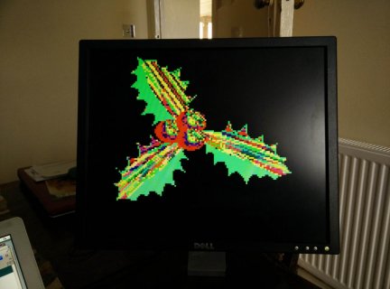
The Teensy3 VGA output now reads a BMP image from SD card to the lcd screen:
Teensy_holly_bmp.jpg
As you can see, its very low res. The teensy reads an 8Bit bmp into the buffer, converting it to 6bits of colour to use the six pins (2 for each of RGB).
This buffer gets loaded in Setup from the sd card. The bmp is only 120 by 100 pixels resolution.
 
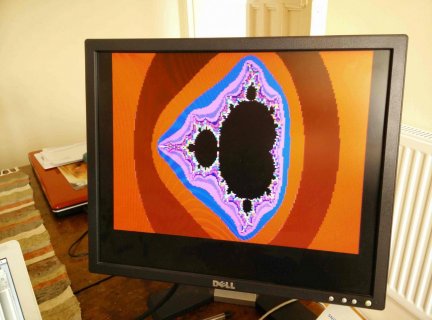
Is that a procedurally generated on the fly, or built at run time before the image was displayed?

How much actual processing time is available here when outside the screen area? I've seen how Atari et al did magic in the retrace but thinking breaking the code up into single line chunks complicates anything you would do in Arduino land.
 
@GremlinWrangler, the mandelbrot is generated in the loop, using maths in for loops, but is super slow, just for the fun of it stuff. It uses so many floats and calcs that it is not much more than a curiosity at present, and a bit of a hello world calculation exercise

I will not be doing anything more with heavy calculation stuff like the above, it was to give an idea of potential image pixel density, and what it looks like. Other generated images in the for loop work well. I am testing the rate of drawing from sd card at the moment. Below video is of for loop generated simple maths


Last edited:
nice work :)

would it be possible to run the code for the vga-output on a teensy 3.6?
and is there any posibility to go higher than 200*200 resolution (maybe in 256 colors too)?

would be nice if anyone knows
 
Status
Not open for further replies.
Back
Top