Frying teensies when using USB power and an external power supply at the same time?

Status
Not open for further replies.

local_dani_21

Well-known member
Hi guys

I'm frustrated because I just fried my third teensy 3.1 and still don't know, what happened (at least I have an idea). Every time one broke it took me a while to realize that the teensy was fried (when powered it get's very hot, isn't registered by the system anymore and it can't be talked to using the Arduino IDE). Therefore I don't know the exact moment when it stopped working; however I think it could be around the time when I added an external power supply while talking to the teensy 3.1 over USB using the Arduino IDE serial monitor.

Here is what I did, maybe you have an idea.

I'm working on a project that in the end will need a lot of power, so there is a power plug in parallel to the rest of the curcuit to connect a 5V / 3A switched and well regulated power supply. Shortly before the last breakdown, I added one of the power consuming parts (a raspberry pi 2 that is connected to a an ethernet shield that is connected to the teensy) and connected the external power supply. The system kept working (as far as I can remember) for a few minutes (I talked to the teensy using USB-Serial in Arduino IDE serial monitor) and then the teensy got hot and stopped working.

Do you know if USB power and an external power supply can conflict and eventually destroy a teensy 3.1?

Thank you very much!

Dani
 
Thank you! I should have asked before ... But out of curiosity: What did actually happen to my fried teensies? How will the setup behave differently once VIN is seperated from USB power?
 
I don't know why your Teensy fried, maybe you actually did some incorrect wiring and accidentally shorted something, if your power supply was greater then 5V and plug it on vin, or a bunch of other stuff could have happened, without your schematics is difficult to tell. You could actually feed voltage back to your computer and/or battery and damage it...

If the microcontroller fried, the only way around would be re-soldering a new one, but that would require some skill to do, and it will not work if any other passive fried with the microcontroller it self.
 
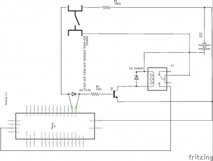
Well here are my schematics (I just cut the Vin-USBpower connection but yet fried and lost my fourth and last teensy 3.1, I'm devastated).

The machines startup is initiated by pressing the power button, which turns the relay on and hence the teensy is powered. As soon as the teensy is running, it pulls D13 high to hold the relay ON, so the button can be released. When the button is pressed again, pin D12 can measure that and then pull the relay down to unpower the circuit.

power_circuit_Schaltplan.jpg

That is the code:
Code:
/*
  Button to turn on and off the power of a curcuit using a relay
  Gemäss finalem Pin-Layout
  Dani Süsstrunk
  11.3.2015
 */

const int powerButtonPin = 14;     // the number of the pushbutton pin
const int relayPin =  20;              // the number of the relay pin

// variables will change:
int buttonState = 0;         // variable for reading the pushbutton status

void setup() {
  pinMode(relayPin, OUTPUT);
  digitalWrite (relayPin, HIGH); // Turn machine on

  // initialize the pushbutton pin as an input:
  pinMode(powerButtonPin, INPUT);
}

void loop(){
  // read the state of the pushbutton value:
  buttonState = digitalRead(powerButtonPin);

  // check if the pushbutton is pressed.
  // if it is, the buttonState is HIGH:
  if (buttonState == HIGH) {    // Taste gedrückt --> Abstellen / Turn off
    digitalWrite(relayPin, LOW); //Strom abstellen
  }
}

Thanks for looking at it. I don't have an oscilloscope, but when pressing the button to turn the machine on, when measuring from GND to Vin, I seem to be getting 10V for a very brief moment (one reading) instead of the 5V I expect. Where would this doubling come from? It would explain the teensy to fry.

Dani
 
Taking a lil stab at this.. In relation to time.. slowing it down.

When you apply power for the 1st time, your transistor will turn on as the program starts (void setup sets it high. Near that time of loop, you turn it off because it now is pulled low by relay pin.
I'm guessing during the time the relay opens and the diode pulses a + pulse back thru the current closed contacts before they open.. kinda like adding..
This is done just before you push the on-off button.

The loop cycles, does this cause pulses to be created? I don't know..
I suggest adding some caps and a zener..5.1 on Vin to make sure.
 
So i guess you are trying to use the Teensy only to accomplish a Soft Latching Power Switch Circuit, did i understand it right? if that is the case, why not just use something like this https://www.pololu.com/product/750 or build a circuit like this https://www.youtube.com/watch?v=Foc9R0dC2iI ?

First, i'm not an expert, I hope Paul or any other expert can come here to comment, but i noticed that you are actually imputing some voltage on Teensy IO's before teensy is actually powered up, I don't know if that is recommended.
 
Indeed, I'm trying to do something like the pololu-product - but tried to invent it myself (with things I hat at hand) (with obviously no luck). Interestingly the circuit worked for quite some time while I had no other consumers as a led. The trouble started, when I added more load (like the RPi2 I mentioned and the ethernet shield [not drawn in the above schematic]).

Thanks for the input. Indeed, I'd be interested in some engieneer-expertise :)
 
Turning off anything with an inductor in series always worries me.

I see you've got a 1N4001 diode in parallel with the relay coil. That really ought to be a fast response diode. One of those 1N4148 would be much better.

Another question to ask is what happens if the other stuff you're powering has inductance? When you turn it off, does it generate a short but high voltage spike? If so, where does that energy go? I must confess, the schematic seems a bit confusing to me... but it looks like any energy stored in series inductance of the switched load can only dissipate by conduction through the VIN pin on Teensy.
 
Thanks for you replies. At the moment, I don't dare trying many more things with my relay. I ordered one of the pololu switches mentioned above (https://www.pololu.com/product/750) and will work from there. And I've started to look for a simple digital oscilloscope (I'm now waiting for a Rigol ds1052e) to be able to investigate things better.
 
Last edited:
Does anyone know if a teensy 3.1 will be damaged if 5V is applied to a pin if the teensy has not been powered? What about applying 5V while it is being powered up? Thank you, Dani
 
Does anyone know if a teensy 3.1 will be damaged if 5V is applied to a pin if the teensy has not been powered? What about applying 5V while it is being powered up? Thank you, Dani

I dont believe that is easy to answer, I personally avoid applying 5V to any of the Teensy 3.1 pins. If you apply voltage to any of the GPIO pins without at-least resistor protection I would say your asking for trouble. Especially during start-up when supply voltages can spike.
 
Status
Not open for further replies.
Back
Top