Best Way To Read up to 50V DC via ADC on Teensy 3.1 ??

Status
Not open for further replies.

solardude

Well-known member
Hey everybody!

I did a search about reading battery voltages over 3.3v using the ADC input on the Teensy 3.1 and I have a good idea of how others are doing this but I want to get some feedback on my specific application since the voltage is a tad bit higher than others are trying to measure.

I'm building a line of products that have solar charge controllers built into them and I want to measure the solar panel input voltage and I will also measure the solar input current via a separate current measurement chip.

The maximum input voltage is 50v DC.

Based on what I have read I think its best to supply the Teensy 3.1 from a regulated 3.3v power regulator that will be powered from a 12v battery. So the Teensy will have a rock solid 3.3v power supply.

I know I can use a simple resistor divider to knock down the solar input voltage to not go above Teensy's 3.3v max ADC input range.

Can anybody provide advice on how to get the maximum ADC resolution from a 50v input thats knocked down to 3.3v via a resistor divider setup?

Here is what SparkFun says about the Teensy 3.1 ADC resolution: 21 High Resolution Analog Inputs (13 bits usable, 16 bit hardware)

I'm not sure what the max resolution is for the ADC Analog inputs. I saw a guy using 12 bits on the forum so I know it will at least do that, but does it go higher?

I assume doing alittle sampling and displaying the median value wouldn't hurt also but this is all new to me so I'm looking for what ever advice I can get before attempting this.

Any and all help is greatly appreciated.
 
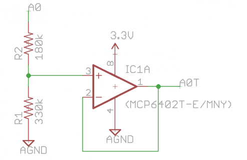
I typically use a circuit like this. It's a simple resistor divider (this one is tailored for 5V to 3.3V translation) connected to a unity gain opamp. The opamp ensures the ADC input capacitor receives sufficient input current to be charged quickly and accurately, even when using high resistor values (which you should, analog inputs should draw virtually no current from the measured system). Make sure you use rail-to-rail opamps, or you will have to provide some offset and headroom between the two rails. You can also place a input capacitor to reduce noise.

adc_opamp.png

A more complex solution is to use a high voltage opamp with a gain factor of less than one (around 0.06 for your case). This ensures an even higher input impedance, but opamps with gain factors <1 are often unstable.
 
Last edited:
13 bits are only usable when using 2 pins for differential A/D conversion. In single ended mode (only 1 voltage towards ground), 12 bits are usable. The latter allow a precision of 3.3V / 2^12 = 0.8mV which should be enough for simple voltage measurement. The resistor voltage divider should have a low inner resistance to prevent errors due to the ADC input impedance, so I suggest building it as follows:

+50V -4.7kOhm- Teensy-Pin -330Ohm- GND

This divider will draw about 10mA from the Solar panels which should be negligible compared to the battery loading current.

You could add some noise suppression by putting a 100nF capacitor in parallel to the 330Ohm resistor.

I want to thank both of you guys for taking the time to write me back :)

Theremingenieur's solution seems like the easiest way to go. Nice and simple and 10mA is indeed no big deal on the solar input side.

I'm assuming that the 10mA power loss is only when supplying 50v and less as the voltage drops?

I just need to set the ADC resolution to 12bit via Teensy 3.1 code to get the maximum resolution.
 
The 10mA is not a power loss, but a current loss ;-) which is proportional to the input voltage.
The power loss is proportional to the square of the input voltage and will thus be only 25% at 25V instead of 50V.
 
Sweet, looks like I know what I need to do now.

I'll report back once I have this up and running.

Thank you very much!
 
I just looked at the detailed specs of the ADC input and you should be safe with 10kOhm/680Ohm too, thus reducing the power loss by 50%, loosing now only 1/4W instead of 1/2W at 50V
 
Thank you very much for double checking this!

The less power loss the better:)

Most of the time the solar input will be in the 18 - 36v range.

So sticking with the 3.3v refrence voltage and setting the ADC to 12bit resolution I should be able to measure down to .08mv resolution? Based on this: 3.3V / 2^12 = 0.8mV
 
No, each measured digit corresponds to about 0.8mV depending on the resistors' tolerances. You should feed one time around 40V into the divider and one time around 4V and look each time at the result of the ADC. With these two readings, you'll be able to establish a calibration function y = a*x + b to print out y as the "true" voltage in form of a float number. If you don't feel like doing these mathematics just publish the two Voltages used (verified with a digital multimeter) and the corresponding ADC readings here and I will do the calculus for you.
 
Recently did some stuff to measure up to 1500V PV strings. Suffice to say, direct divider network would require mucho R, so mucho noise. Prefer to use an isolated current mirror to measure stuff > 60V to avoid loss of resolution due to circuit noise.

Will have to ask boss if circuit can be posted.
 
Yea 1500v is up there :cool:

So does the noise come from the fact that your measuring such a large range of voltage that even a small amount of variation ends up creating a wide range in the voltages output readings? Sorry I'm learning here.

I appreciate you trying to share the circuit.
 
Cannot provide schematic. The circuit and layout was somewhat weirdo because was trying to build something conformant to UL1741/IEC62109-1, so there was much stuff that you would not need or want.

But can say this - look at linear optos (for example IL300) and basic current mirror circuits.
 
Recently did some stuff to measure up to 1500V PV strings. Suffice to say, direct divider network would require mucho R, so mucho noise. Prefer to use an isolated current mirror to measure stuff > 60V to avoid loss of resolution due to circuit noise.

Will have to ask boss if circuit can be posted.

Large R network with filter cap at the bottom along with an opamp combined with software averaging is how its done where I work.
 
No, each measured digit corresponds to about 0.8mV depending on the resistors' tolerances. You should feed one time around 40V into the divider and one time around 4V and look each time at the result of the ADC. With these two readings, you'll be able to establish a calibration function y = a*x + b to print out y as the "true" voltage in form of a float number. If you don't feel like doing these mathematics just publish the two Voltages used (verified with a digital multimeter) and the corresponding ADC readings here and I will do the calculus for you.

@Theremingenieur - I finally picked up the resistors and not have test results for you so we can create the Analog Read code with the correct calculations.

I only have a 30v power supply so I'm going to have to give you 3v and 30v readings, so hopefully that will work.

Here is the voltage I get when I feed the resistors:

3v = Bounces between 0.192 & 0.193 mV

30v = 1.941 mV

Looking forward to seeing how the calculations work so I know how to do this in the future on other projects also.

I'm loving the Teensy 3.1 dev board, its everything I need that all the other boards didn't have.
 
Here is the formula I use for my Electic gocart using your divider. You can make it even more accurate if you measure the resistance of both resistors. And you can make it much smaller, I wrote it out so you can see what is happening.

Top half converts ADC value to a voltage, bottom takes care of the resistor divider.

(2^12 - 1) (R2 / R1+R2)
(3.3V * (adcvalue / 4095)) / (680/10680)
 
Status
Not open for further replies.
Back
Top