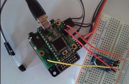
Mic In on Teensy Audio board

Status
Not open for further replies.

ardutoni

New member
Hi

i'm a Teensy Newbie.
and will ask if they are setup examples. I like to use the input and mic channel. Understanding the FFT library documentation the audioInput (mic/line in) has the same parameters, so it will recorgnized the signal automatic?
i will use this microphone https://www.adafruit.com/products/1713 that gaves out/gain/vdd/ground, so i have to solder the out > mic and gnd > gnd. What about connecting the vdd at audio shield - the 3.3V on the right corner is dedicated for the current?

AudioInputI2S audioInput; // audio shield: mic or line-in
AudioConnection patchCord1(audioInput, 0, myFFT, 0);

thanks in advance
 
The mic input is intended for an electret microphone. The board you are using already has a line-out signal, so connect it to line-in.
For an example look at: File - Examples - Audio - Analysis - FFT.
With the 3v3 you mean the 3 pins that are intended for the potentiometer (GND-VOL-3.3V)? Those could be used.
 
sounds comprehensible, i'm using the mic-breakout with arduino also on an A-port. So, with the audio shield i use one of the Input (L/R) channels, the G on the Input means Ground or Gain,
and what connection-PIN gives the power to the microphone.

Yeah, the connection at the corner labeled GND/VOL/3V3/
I'm using exactly that FFT sketch
 
thanks for your suggestion, works fine at the input channel.

I have a further question, busing the smart-matrix and audio shield in a stack, to get audio IN (16 bit sampling) and visualizing with FFT on LED Matrix.
Can be there a conflict by using i2S und i2C once at time, and which is the appropriate stacking. My setup starts with Smartmatrix, following with audio shield and at the top Teensy 3.1 how it shows the picture attached.

teensy_smartmatrix_audioshield.jpg
 
The audio shield uses I2C to control parameters on the audio shield like output levels, tone controls, etc. Mostly this is just at startup. There is no problem using multiple I2C devices as long as they have different addresses.
 
thx for explanation of i2C matter!
at least the board-stack with smart-matrix, audio shield, teensy results in a message from Arduino IDE '..there is no Teensy found on USB..', also nonluminous LED at the board.
to smart-matrix the current was plugged-in, so there is no reason..
 
at least the board-stack with smart-matrix, audio shield, teensy results in a message from Arduino IDE '..there is no Teensy found on USB..', also nonluminous LED at the board.
to smart-matrix the current was plugged-in, so there is no reason..

That problem is very unlikely to be only I2C.

If Teensy isn't responding at all, you've probably got some sort of other hardware problem, like power, that's preventing Teensy from running at all. As a first step, I'd check the 5V and 3.3V power with a voltmeter. Also check the PROGRAM pin, which should be 3.3V normally and it should go to zero when you press the button.
 
Status
Not open for further replies.
Back
Top