Is there a market for a Teensy 3.1 48 pin ARM stamp?

Status
Not open for further replies.
The Teensy has little to no room left over, even if the planned MKL02 transition potentially opens up 5mm^2 of board space... (whooohoo!)

I'm going to use the newly opened space, plus space gained by removing the input diode, to add a durable 3.3V regulator chip.
 
I'm going to use the newly opened space, plus space gained by removing the input diode, to add a durable 3.3V regulator chip.

Paul,
I think one thing that keeps getting people is that a full connection diagram is not given with the updated libraries. The assumption is made that people understand what a 100mA limit is when they may in fact do not. A lack of full wire diagrams for libraries probably contributes to the many "Dead Teensy's" you have to deal with on a weekly basis.
 
I'm going to use the newly opened space, plus space gained by removing the input diode, to add a durable 3.3V regulator chip.

That's a great idea, esp. if the thing includes a auto-shutdown on current over-draw. FWIW, I have had good luck with the TI TLV series, which offer allegedly infinite operation with a short circuit. The X2SON version of the VR is only 1x1mm (!!!), my experience is limited to the SOT23. My guess is that the former needs more thermal land area to dissipate any accumulating heat than the latter.

I'd even consider sacrificing the 0.5A polyfuse (or make it optional via pads on the underside) if the VR has this auto-shutdown built-in. That is, bring VUSB to polyfuse pads on the underside but leave them unpopulated. Then, if a user wants to make use of the VUSB pin, they have to solder on the polyfuse or short the pads first.

If there is room left over (extremely unlikely, I know!) it would be awesome to make use of a PTH USB connector since they tend to be harder to extract accidentally from the PCB than the SMD kind, and easier to repair.
 
Last edited:
FWIW I use the TLV70733 and TLV73333 in the X2SON package frequently. They take up to 5V5 input. The former has a 200 mA current limit, the latter 300 mA. As regulators, they work reliably as one would expect, but the claim is they can work without bypass caps when powered directly from a LiPo battery (at least the 73333). I always use 1 uF bypass caps anyway, but in a space constrained application this can be a real plus.
 
The next Teensy 3.x board will have a LP38691 voltage regulator.

For continuous operation, the heatsinking available from the metal layers on the PCB limits power dissipation to about 1 watt. Even though the LP38691 is rated for 10V input and 500 mA output, sustaining both of those would result in about 3.35 watts power dissipation. But my hope is the 10V capability will allow future Teensy boards to survive abuse that currently kills the hardware.

The higher output current will let Teensy directly power the ESP8266 Wifi and W5200 Ethernet modules too. :)
 
At least if I understand the data sheet correctly, I guess one avoids issues with the USB cable being suddenly pulled and the regulator being backfed with the 'enabled' version of that voltage regulator...

Paul is spot on though choosing a chip with a wider input voltage rating than the TLV series because you never know what people are throwing at the Teensy. Some of those cheap switch-mode power supplies have much higher output voltages under low-load than they should!

I also wonder if the D33 issue can be addressed with this revision (that is, a transition to SWD potentially opens up a line or two over EZPort). Not sure how you'd detect the right chip via Teensyduino, however.
 
I recently spent hundreds of dollars of frustrating time because the teensy doesn't have a SWD debugger. Guess I'll have to try the "solder tiny wires directly to cpu" modification. At least make some pads for these pins.
 
I recently spent hundreds of dollars of frustrating time because the teensy doesn't have a SWD debugger. Guess I'll have to try the "solder tiny wires directly to cpu" modification. At least make some pads for these pins.

I wish there were a hardware or software way to toggle the SWD signals between the PJRC bootloader chip and pads or a connector for a user's SWD.

Or is there a way to hold the bootloader chip in reset to cause the SWD signals to go to floating? Then one could turn on the SWD pod and run a hardware debug session. Including flash downloads.


This is a big deal for some, as above.
 
Or is there a way to hold the bootloader chip in reset to cause the SWD signals to go to floating?

This is on my feature list for Teensy3++.

I plan to dedicate pin 3 on the bootloader chip as an active-low request to release the SWD pins. I'm going to add a location to solder a 5-pin connector to access the signals: GND, EN', SWC, SWD and RST, where EN' is the pin to pull low to get the bootloader to tri-state those signals. The intention is you'd wire EN' to GND in the connector, so the signals are automatically available when you plug the cable in. Of course, the bootloader will go into an inactive mode as long as EN' remains low, but when you remove the cable (or allow EN' to return high and of course stop driving the 3 signals), Teensy3++ will return to normal bootloader operation.
 
@paul
That's great!

I've found that with my $20 (STM) SWD pod, if it's connected to the MCU but the USB power to the pod is absent, it causes the MCU to not startup. Perhaps it is dragging down reset or something simple like that.

I bring that up, as I foresee, for the lazy ones like me, the need for a toggle switch or some such so as to not have to unplug re-plug the SWD connector.
But in reality, many/most would be flashing the MCU via the SWD and not the bootloader, during development. So the SWD could just remain plugged in.
Thereafter, perhaps the .hex would be distributed and used with the USB bootloader.
 
Are these cheap china 5€ ST-LINKv2 compatible, and is it possible to use them ?
 
Last edited:
I don't know. I've only used the real ST-Link v2 SWD pod and it sells for $21 from Mouser, etc., reputable companies. Sure a lot better than the $500 J-Link I have from years back.

I avoid important stuff like tools that are China clones.

Perhaps there are other low cost SWD pods with good IDE support; that's the key thing with cheap-o's and clones. The USB side and drivers are not standardized, hence the need for name brands.

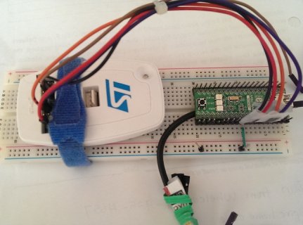
I have several ST-Link v2's. enclosed is a photo of one patched to a low cost 168MHz ARM STM32F415 board. (Wish I could do this with T3)

Being SWD standards compliant, I'd think, but have not proven, that the ST pod will work with other MCUs brands. It has drivers and IDE debug support from most popular IDEs: Eclipse/GCC, IAR, Keil, Rowley/GCCand VisualGDB (cheap, good). I don't know about Mac or Linux - probably so. Don't know about Freescale's KDS/Eclipse.


IMAG0792.jpg
 
Last edited:
Good to hear that a future teensy will have access to debugging pins. Until then, one option may be to use a FRDM-K20D50M (same cpu as teensy 3.0) + pyOCD for teensy development. I'm going to try it.
 
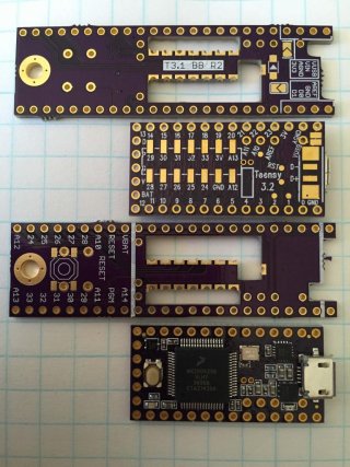
I just received 12 of HWGuy's brilliant boards from OSH Park. His R2 version has an enlarged cut out for the crystal, and is a great looking board layout.

The only slight gotcha is that I also ordered a bunch of new Teensy's at the same time, which due to the change-over arrived as the new 3.2's... well Paul shifted the "rst" pad slightly, and HWGuy had cleverly aligned one of his "mouse holes" to land on the old rst pad location. I'll figure out some way to fix it with a piece of foil soldered between the boards, until HWGuy revs to R3. :rolleyes:

Although this thread has gone all over the place, this board is a brilliant solution for people who want easy access to all the pins, in a breadboard-friendly layout, with a drop-dead simple solution to the soldering on the bottom pads.

Kudos and thanks to HWGuy for doing the design and sharing it out on OSH Park. And thanks to iwanders for the original inspiration too.

--Jon

P.S. If anyone can find a decent part number for Digi-Key, Mouser, Newark, etc. for the long centered header pins to join the boards, I'd appreciate it. The "extra long headers" from Adafruit and the "long centered" from Sparkfun are the right style, I just haven't been able to find a domestic supplier part number yet.

Teensy 3-Breakout Board-small.jpg
 
Last edited:
I just ordered some Samtec TSM-107-01-T-DV Connector Header, 14 position, 0.1" dual SMT headers from ebay: http://www.ebay.com/itm/201239380450?_trksid=p2060353.m2749.l2649&ssPageName=STRK:MEBIDX:IT. As far as I can tell, these would match the 7x2 data pins underneath the Teensy.

I have not been able to find 24 position female stacking headers, but dipmicro has 40 position headers that you could cut down. Note, they are evidently going on vacation, and closing the store for 3 weeks, so if you order from them, it needs to be by Monday morning. While they are based in Niagara Falls, Canada, they do a mailing 2x week from the USA. I've various bits and pieces from them (my order should be in my PO box, and I'll pick it up tomorrow): http://www.dipmicro.com/store/HDR40X1FL.

If you are wanting pins like the Adafruit extra-long pins, I believe you can use multiple of the Adafruit pins (the female headers can't be used in adjacent holes without sanding down one end). I did see this ebay seller that has 40 pin long pin variants: http://www.ebay.com/itm/40-Pin-Male...ng-Lot-of-5-/191656350633?hash=item2c9f9bd3a9

I've also discovered that with the normal male pins, you can press the plastic down to lengthen one end.
 
I didn't order the HWguy's R2 board from OSH yet - hoping there is a worthy easy cut or reroute / larger pad for an R3 version that could reach to the RST on 3.1 and 3.2?
 
I am after a part number for the long type headers, centered on each side, that Adafruit and Sparkfun sell. Somebody must carry them, but for the life of me I can't figure out how to find them in the parametric searches on Digi-Key et al.

The datasheets at both Adafruit and Sparkfun are the same part, made by 4UCON, and clearly lots of other sellers have found them.

I don't think the stacking style headers would work the way these boards have to be soldered together, unless I'm missing something. Maybe you have a different arrangement in mind?
 
Last edited:
Well... If HWGuy does an R3 update for the Teensy 3.2's, and if somebody else wants some already made R2 versions of HWGuy's boards, to mate with some 3.1's they have laying around, I'm happy to pass some of the ones along that I just got (they were $8.30 for 3, I got 12).

Just before I saw HWGuy's board on this thread, I had just finished soldering pins onto the last of my 3.1's. It didn't occur to me when I ordered everything from OSH Park that I'd be slightly out of sync between the two boards. Oh well. The breakout board is fantastic and I'm sure I can make them work with some hack.
 
Ok, I played with it tonight with my one SMT header, and my 20-pin stacking headers. It looks like I did not understand the layout of HWGuy's board. I thought that it was similar to the other two extension platforms I've seen:

On these boards, you solder a 7x2 SMT header to the data pads, and the board has through holes (in the case of the Talldog board) or female mounting holes (in the case of the Petit Studio board) that the SMT fits into. With the SMT header, you have to be real careful not to rip the pads off. Alternatively instead of the SMT header, you use the Jimmayhugh method: https://forum.pjrc.com/threads/26071-Using-all-Teensy3-x-pins-with-a-socket. In either case, there is space between the Teensy and the extender board. I must say, my faith in my soldering skills has not been up to tackling these boards.

However, HWGuy's board is different. It is made to sit right on top of the Teensy board, and you don't need to solder any pins to connect the two boards. Instead you use a solder trace to connect the pads to the castellated holes. It looks like a simpler technique.

Now for the female stacking headers, I was planning on cutting up the 40 pin headers to 24 pins, and that would allow me to put the board in a perfboard and then have female sockets (like a breadboard) to attach wiring for temporary assignments before I make more permanent wiring to the perfboard.
 
Last edited:
I just received 12 of HWGuy's brilliant boards from OSH Park... well Paul shifted the "rst" pad slightly, and HWGuy had cleverly aligned one of his "mouse holes" to land on the old rst pad location. I'll figure out some way to fix it with a piece of foil soldered between the boards, until HWGuy revs to R3.]

Maybe you can use something like this flat (1.5mmwide x 0.2mmthick) pretinned copper solar panel tabbing wire to bring the relocated Teensy 3.2 reset signal over to the solder point on the Rev2 HWGuy breakout board.
http://www.ebay.com/itm/100-feet-TABBING-WIRE-for-Solar-Cell-DIY-Pre-soldered-/171859110829
 
Last edited:
P.S. If anyone can find a decent part number for Digi-Key, Mouser, Newark, etc. for the long centered header pins to join the boards, I'd appreciate it. The "extra long headers" from Adafruit and the "long centered" from Sparkfun are the right style, I just haven't been able to find a domestic supplier part number yet.

I've searched the drawings/prints from Samtec/Molex/FCI/Harwin/TE(AMP)/3M for pin headers with post and tail length 5-7mm. (7mm is too long)

KK® Interconnect System 42375 from Molex.
42375-3568
42375-3693
42375-3728

But they are not in stock.

FCI has a few matching parts, but they are all marked as obsolete.
68032-108HLF http://portal.fciconnect.com/Comergent//fci/drawing/68000.pdf


Code:
Sullins Connector Solutions 

HEAD: 5.84MM 
TAIL: 5.84MM

PIN QTY: 40

TIN
PREC040SABN-RC          DIGI-KEY: S1022EC-40-ND

Code:
3M - 929 SERIES

HEAD: 5.97MM
TAIL: 5.33MM

PIN QTY: 36

GOLD
929647-02-36-I          10 μ” ALL OVER, PBT INSULATOR     MOUSER: 517-647-02-36           DIGI-KEY: 929647-02-36-ND 
929647-02-36-EU         10 μ” ALL OVER, PCT INSULATOR     MOUSER: 517-929647-02-36-EU     DIGI-KEY: 929647-02-36-EU-ND

TIN
929834-02-36-(BLANK)    100 μ” TIN-LEAD, PBT INSULATOR    MOUSER: 517-834-02-36           DIGI-KEY: 929834-02-36-ND
929834-02-36-RK         100 μ” TIN-LEAD, PCT INSULATOR    MOUSER: 517-929834-02-36-RK     DIGI-KEY: 929834E-02-36-ND

Material: Glass Filled Polyester (PBT) or High Temperature (PCT)

http://multimedia.3m.com/mws/media/43897O/3mtmpinstriphdr-100-100x-100-929-series-ts0769.pdf

In my oshpark pictures, head & tail are 6.2mm and that's a bit too long. It seems that something like 5.08mm (0.2 inch) would be the optimal length.


Updated version of the adapter board for Teensy 3.2: oshpark and image. The board is not tested and at the moment I have no plans to order one.
 
Last edited:
I just received 12 of HWGuy's brilliant boards from OSH Park. His R2 version has an enlarged cut out for the crystal, and is a great looking board layout.

The only slight gotcha is that I also ordered a bunch of new Teensy's at the same time, which due to the change-over arrived as the new 3.2's... well Paul shifted the "rst" pad slightly, and HWGuy had cleverly aligned one of his "mouse holes" to land on the old rst pad location. I'll figure out some way to fix it with a piece of foil soldered between the boards, until HWGuy revs to R3. :rolleyes:

Although this thread has gone all over the place, this board is a brilliant solution for people who want easy access to all the pins, in a breadboard-friendly layout, with a drop-dead simple solution to the soldering on the bottom pads.

Kudos and thanks to HWGuy for doing the design and sharing it out on OSH Park. And thanks to iwanders for the original inspiration too.

--Jon

P.S. If anyone can find a decent part number for Digi-Key, Mouser, Newark, etc. for the long centered header pins to join the boards, I'd appreciate it. The "extra long headers" from Adafruit and the "long centered" from Sparkfun are the right style, I just haven't been able to find a domestic supplier part number yet.

View attachment 5112

wait, are you saying oshpark is sending out 3.2 and not 3.1?
 
well, when I placed the order, it was for 3.1, now I checked the status, they replaced it with 3.2 without notifying me.
I had intended to use it on boards with the 3.1 pad placement. I just sent them an email to make sure they send me a 3.1.

edit: ok, I got a reply from oshpark and they are cancelling my (breakout board) pcb order. I was not expecting a reply at 1:40 in the morning. :)
 
Last edited:
Status
Not open for further replies.
Back
Top