Teensy 3.1 external power help.

Status
Not open for further replies.

Pointy

Well-known member
Hi guys,

As the weather was horrendous here yesterday, I did some more work on my project and started working on the PCB design. I am more of a software guy and while I have some very basic knowledge of electronics I wuld love some help with this part.

So my Teensy 3.1 is mainly being used to monitor various sensors and switch mains voltage devices on and off. I am using one of these 8 way relay modules. The relays on these modules are Songle SRD-05VDC-SL-C, which draw just over 70ma. I may want to add another bank of 8 in the future so I need to take this into account. I am also using the Wiz820+SD Adaptor, utilising both the ethernet and SD card. (Not sure how much current the Teensy 3.1 + adapter will use, any ideas?)

I want to power it from a single supply and was just going to use a 5v power brick connected to a DC jack on my board. I this wise or should I go for a slightly higher voltage supply and include a voltage regulator circuit on my board? If it's the latter can someone suggest the best components to use with a little schematic diagram? I am guessing the 2a would be enough, but maybe 3a to be extra safe.

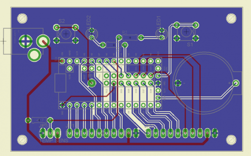
Here's very rough first draft of the PCB...
pcb1.png

Regards,

Les
 
The W5200 controller ic on the Wiz820 module consumes up to 175 mA, sd cards 80-100 mA and the Teensy 3.1 ~30-40mA + current for gpios (led, ...).

I like to have a wide input voltage range, that's why I include a voltage regulator on my boards. For 2-3A output current, I suggest to use a dcdc converter module like this one: Murata Power Solutions OKR-T/3-W12-C

a few hints about your PCB
  • The DC Jack is in front of the USB connector.
  • The temp sensor is not connected to the Teensy.
  • Try to avoid using pin D33.
  • The common way to connect the DC Jack/Plug is: sleeve: GND, tip: positive voltage. (It's inverted on the pcb)
 
The W5200 controller ic on the Wiz820 module consumes up to 175 mA, sd cards 80-100 mA and the Teensy 3.1 ~30-40mA + current for gpios (led, ...).

I like to have a wide input voltage range, that's why I include a voltage regulator on my boards. For 2-3A output current, I suggest to use a dcdc converter module like this one: Murata Power Solutions OKR-T/3-W12-C

Thanks for the great feedback and very well spotted on the newbie errors! I'll take at look at that converter too.

  • The DC Jack is in front of the USB connector.

I would have got that one when I did my paper layout test. Honest! ;)

  • The temp sensor is not connected to the Teensy.

Slight error on the schematic.

  • Try to avoid using pin D33.

I don't actually need all the digital pins I was just bringing them out for possible future use. (The LEDs are an afterthought for diagnostics) Can I ask why I should use D33 though?

  • The common way to connect the DC Jack/Plug is: sleeve: GND, tip: positive voltage. (It's inverted on the pcb)

That's me miss interpreting the schematic symbol.:eek:


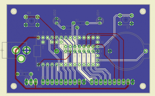
Here's a quick rework...

pcb2.png

Regards,

Les
 
Reading the pin33 caveat link - it says 'use as output only' - in this case it is running an LED. Would that not qualify - i.e. would the pull-up get zero'd by the resistor through the LED?
 
Pin 33 is a non-maskable interrupt. When it's low on reset the Teensy enters EzPort mode (some sort of direct flash programming mode)
more information: https://forum.pjrc.com/threads/2482...w-freezes-teensy?p=50667&viewfull=1#post50667


Thanks for the heads up.

With regards to the OKR-T/3-W12-C, have you used them, as I have a few questions?

  • The data sheet says the trim resistor must be 1/10w 0.5%. Is it really that critical,? (I think I have some 1% metal film resistors)
  • Should I add any capacitors on the input/output?
  • As I am not going to use the on/off control, do I just leave the pin open?

Thanks again,

Les
 
I've never used the OKR-T/3-W12-C, it was one of the first search results on mouser.com

The data sheet says the trim resistor must be 1/10w 0.5%. Is it really that critical,? (I think I have some 1% metal film resistors)
No it's not that critical.

example:
Rtrim = 270Ω (Vout: 4.97V)

1% tolerance: Vout 4.93V - 5.01V
0.5% tolerance: Vout 4.95V - 4.99V

and then there are other errors which affect the output voltage:
- Rtrim resistor: temperature coefficient
- DC/DC converter: Temperature coefficient ±0.02% per °C. of Vout range
- DC/DC converter: Accuracy (50% load, no trim) ±2 % of Vnom

Should I add any capacitors on the input/output?
(Yes.) The size of the caps changes with different use cases. The datasheet mentions that the converter will operate with no additional external capacitance, but the same datasheet recommends installing caps at Vin and Vout

You have to find out the appropriate values.

Starting values for the caps are:
Cin: 1x 10μF (50V low-ESR ceramic/polymer)
Cout: 1x10μF & 1x22μF (>=10V low-ESR ceramic/polymer)

As I am not going to use the on/off control, do I just leave the pin open?
Yes


From the datasheet:
CAUTION: This product is not internally fused. To comply with safety agency certifications
and to avoid injury to personnel or equipment, the user must supply an external fast-blow
fuse to the input terminals.

For Vout 5V, Vin min is 7V (Vout+2V).
 
Thanks again for you guidance.

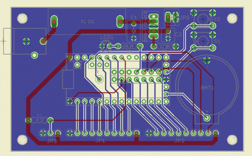
I have added the DC converter, fuse, 5v connector in case I need it and tweaked the layout. I also removed one of the LEDs.

Here's the latest version of the PCB...

pcb3.png

Regards,

Les
 
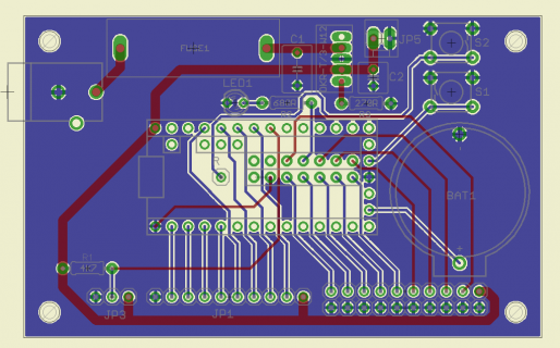
Forget the previous one, there was an overlap error and I made some more tweaks as I thought it wise to have some gnd connections for the input sensors/switches. I also hooked up D33 again, as I believe it can be used as an output, and also the issue may be fixed in a future firmware update. (I don't need it at present, but it maybe be handy in the future)

pcb4.png

Regards,

Les
 
Was looking for stuff as example for nephew and noticed this (teaching the boy PCB layout w/kicad). For the stuff done for employer, have noted that use of 'analog ground' vs the power ground can make a discernible difference for some stuff. You may wanna consider providing separate circuit nodes for pwr/dig and analog. In fact, like to use separate layers for each one, but mostly because of all of the other weird stuff connected to the processor module.

On similar note, am feeling quite smug because was able to convert my nephew to our teensy religion. We grow stronger every day. Long live the PJRC Empire.
 
Status
Not open for further replies.
Back
Top