"Power isolation" circuit/board for Teensy 3.1?

Status
Not open for further replies.
The best way would be to use a stand alone teensy connected to a battery to isolate it. The interface circuit they sell works at 3.3v so you can use the teensy's 3.3v out to power it.

From what i read this sensor "reads" a small variable frequency AC current from the media (water) to get conductivity, this is supplied and processed by the EC circuit board. Well, at least that is what I understood it to be. So any other sensors that are sensitive to this AC current could be effected, if they are close enough.
 
That would isolate the probe but would drastically increase the complexity of my setup. I'm also reading dissolved oxygen, pH, and temp and sending all four to a cell phone via bluetooth. I'd need to communicate between the two Teensies (Teenys?) both to provide the temperature for a temperature compensated reading and to get the conductivity results back. And, would the communication path compromise the isolation?

Thanks,

Eric
 
I think that isolator circuit could be used, it claims to isloate the power and data lines to the EC circuit board. How do you plan to power all this, maybe a schematic showing all the connections would be best?
 
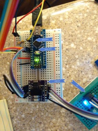
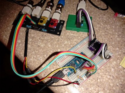
Hmmm...I might try fritzing, but in the meantime, here's a photo of the test setup (using a 5v Arduino Nano) with the DS18B20 temperature; Atlas-Scientific DO and pH (on their I2C board), and Atlas-Scientific EC and PWR-ISO. The bluetooth device isn't currently connected. I'm running all the probes in I2C mode. I plan on powering everything with a 4xAA pack (3xAA with the Teensy). Test setup is using USB power.

2015-07-13 21.05.17.jpg2015-07-13 21.04.42.jpg

My code is running on the Nano, but I'd prefer the flexibility of the multiple serial interrupts of the Teensy for the Bluetooth. I can live with this if I need to.

Eric
 
Last edited:
those PWR_ISO boards run at 32mA idle with everything else hooked up those 3AA won't last long. I would look at a lipo battery pack. Also I cant see any pics?
 
I need the array to work through a field session of 4-5 hours (this whole thing gets shoved in a water-proof case and attached to a kayak) and have the batteries changed/charged by non-technical users, e.g. students. Avoiding the complexity of lipo charging and over/under protection at the moment. That'll be one of my next steps once I'm getting decent readings from the probes (have three setups right now -- none agree with one another).

Eric

P.S. Re-added images. Hope they're visible now.
 
Constantin -- this is a bit beyond my technical skill to purchase the correct sample and use. And, I'm trying to avoid multiple MCUs if I can. Thanks, though!
 
Agree re need to limit MCUs.

Looked at the ISO board. To me, the issue is not related to 5v - you'd simply yank the right resistors and replace them with ones that work the opto-isolator at 3.3v. I had to do that with a board here with relays - it was set up for 5v. Removing the 0805 resistors was easy and in my case they used a 1k resistor for each channel. I replaced them with ~600 ohm resistors and all was well.

The Adum chip can also be used for any serial bus you're trying to isolate. Yes, it's power hungry but you could elect to power it selectively, ie only apply power to the circuit as needed. However, if the power limiting resistors on that opto board are easy to reach then I'd measure them, hit them with a good iron, remove them and replace them with resistors that will work at 3.3v.
 
Last edited:
Status
Not open for further replies.
Back
Top