is this project possible?

Status
Not open for further replies.

raflyer

Well-known member
Hi all,
I have a synchro to digital chip I need to interface to a Teensy 3.1. It outputs a 14bit word which i will use 14 digital inputs to read the data with the following bit weighting. See attached sheet. I then need to output the decoded input as float of 0 to 360 degrees.
 

Attachments

  • SD.pdf
    174.8 KB · Views: 173
Did you have a specific question about some part of doing this?

Seems like you could just read the 14 pins and add each one's weight.

Code:
float deg = 0.0;
if (digitalRead(1) == HIGH) deg = deg + 180.0;
if (digitalRead(2) == HIGH) deg = deg + 90.0;
if (digitalRead(3) == HIGH) deg = deg + 45.0;
if (digitalRead(4) == HIGH) deg = deg + 22.5;
// etc

There are more efficient ways, but maybe try the simplest first.
 
Rob,
I guess it's about your 737-simulator, right?

What instrument uses this? When I built my simulator based on an old ATC-810 panel (http://www.mooreair.com/PHOTOS/ATC 810/ATC810detail.jpg), I was having a similar problem with the OBSs. The instruments were using a resolver (for those who don't know - like me back then: https://en.wikipedia.org/wiki/Resolver_(electrical)).

I ended up producing a 30Hz AC sine wave through software (make sure the frequency matches your resolver specificiation) and measuring AC levels on the two orthogonal coils. That worked fine on the Teensy 2++ with some analog interfacing (http://www.ti.com/lit/an/spra605/spra605.pdf) and appropriate calibration code. I also needed an additional external dual ADC converter to read two analog values simultaneously. With Teensy 3.1's analog output and dual ADC, this should be a lot easier.

Now, that chip you mentioned (SDC/RDC 1740/1741/1742) seems to have everything integrated. Paul's code is a simple example how to read the angular value and it should work fine. However, do you actually HAVE that chip? Digikey mentions whopping $1500 for a single one. There are cheaper alternatives, like the $17 AD2S1210 (http://www.analog.com/media/en/technical-documentation/data-sheets/AD2S1210.pdf), which comes with an SPI interface and will require additional software to read and write it.

So, if you already HAVE the SDC/RDC, consider yourself extremely lucky. If you don't, you might want to check other software and/or hardware alternatives.
 
Last edited:
I actually bought 2 brand new chips for 30.00 off ebay. :) Surplus market is awesome when you catch the right part at the right time. Yes this is to read my heading and Course outputs from the AP panel. I think 1 Teensy 3.1 at 96mhz would be fine reading just these 28 inputs and keeping track of the position? Or should I use one Teensy per chip? Paul's idea is simple and I like it as my being so new to programming it makes sense to me. I'm sure there are better ways but without some hand holding in the programming I would be lost.
On a side note, I'm going to try the long dataref this weekend so Hope to have some feedback for ya. :)
Rob
 
That's great. Now, in my case, the position of the OBS disc was sensed with a resolver without any detent (it rotates freely and doesn't "click").

For using course and heading from the AP panel, maybe something like the Elma E37 might be more interesting. It's a dual rotary encoder with 16 detents per revolution and an additional pushbutton on the inner axis. So, you have an inner and and outer dial that you can rotate and additionally you can press the inner axis. Actually, that's what the Garmin G100 and various autopilot panels use.

I haven't found this encoder on Digikey or Mouser, but there's a guy in the UK that sells them: http://www.leobodnar.com/shop/index.php?main_page=product_info&products_id=196. The ones I ordered arrived within a few weeks. Teensy's Encoder library has an example of how to use two knobs.

In terms of performance, don't worry. A single Teensy easily handles both inputs for either solution (resolver or encoder). My ATc-810 has hundreds of digital outputs (each annunciator and each radio frequency 7-segment digit is one bit), dozens of analog PWM outputs (one for each analog instrument), dozens of digital inputs (each switch is one bit, each radio digit selector is three), and dozens of analog inputs (yoke, pedals, ...). Plus the "special" I/O, like the OBSs (sine wave generator and resolver input), artificial horizon (PIT), etc. All of this runs on two Teensy 2++ and it works fine. Of course there is some additional hardware like some looooong 74hct525 shift register chains, analog level converters and analog filters (see above). But I don't have any performance issues. Two Teensy 2++s.

When you interface with the RDC/SDC chip, just be aware of the voltage levels. The chip runs on 5V and outputs 5V. Teensy 3.1 runs on 3.3V, outputs only 3.3V but can handle 5V on its inputs. Teensy 3.0 and LC are NOT 5V tolerant. If you supply 5V on their input (which an external RDC/SDC 174x would do), you will damage them if you don't take additional measures. I know that you're using some LCs, so take care...

...Anxiously waiting for your report on long datarefs...
 
... reading just these 28 inputs and keeping track of the position...

With this RDC/SDC 174x chip, you only need 8 inputs. The chip has 2 'banks' for the 14 total outputs, and you can enable them individually. So connect the upper bank (bits 1-8) pins in parallel with the lower bank (9-14), and use enable1 and enable0 alternatively to read them. You can use 2 resolvers and combine all 4 banks to one 8-pin port on Teensy, just enable appropriately.
 
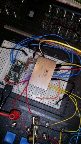
Thanks Paul!! Success has been achieved with the temp breadboard setup. Now I need to design the PCB for all of this. Thanks All.
Rob
synchrochip.jpg
 
Rob, I can't reply to your private message. The forum software tells me that you're out of quota and have to delete some private messages before I can send you more.
 
Status
Not open for further replies.
Back
Top