Multiple power sources for teensy (and also supplying power)

Status
Not open for further replies.

timmyt

Member
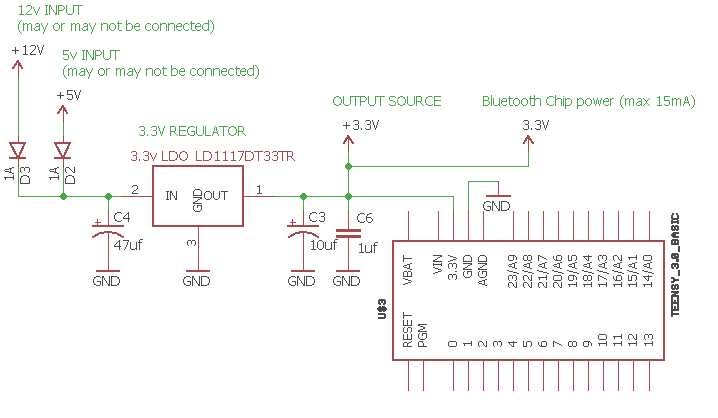
I am using the teensy 3.1 in a project in which it may be powered by either 5v or 12v (probably only one or the other. It is unlikely but possible that it may have both connected at the same time)
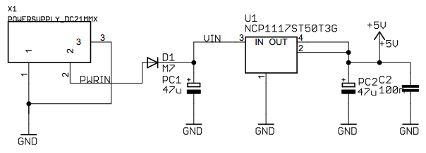
The arduino UNO says that it can take input power of 7-12v and in its schematics it shows this
U1ZhvGS.png

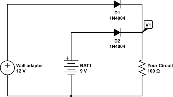
Also I found this which shows multiple power sources
kSxAa.png


Also, I need to supply 3.3v power to something. I know that the 3.3v pin on the teensy can supply up to 100mA, so I was just going to use that. But since I was worried about something maybe drawing too much power I thought it would be good to put a 75mA resettable fuse on it (for a bit less than 100mA to be safe?)

And so I came up with this:
6Xg4gqU.png


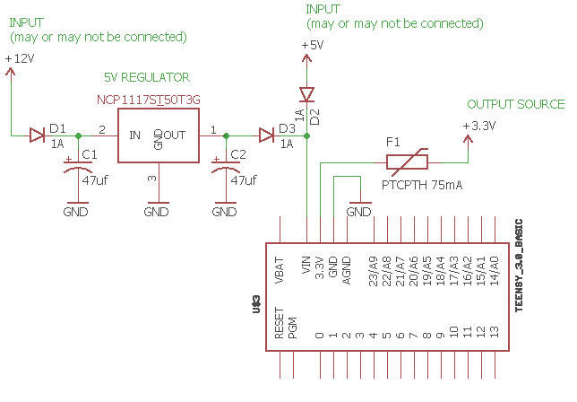
Just wanted to post this here and see if anyone can see something wrong with it or a better way to do it since I have never done anything like this before. I am not entirely sure about how to choose the capacitors for this but I am just copying the arduino schematics.
Also what's with that extra 100nf cap on the right side of the arduino power circuit? Do I need that?
 
The basic design of the circuit is sound but a couple of points:
You probably don't need the diode D1 IF you can be sure 12V will never be connected reversed. If that's possible then leave it in.

The voltage at D3/D2 will be ~0.5V below 5V. This will not matter for your circuit since the T3 will run happily on that, but watch out for anything else that really needs that full 5V supply.

The capacitors are:
https://en.wikipedia.org/wiki/Decoupling_capacitor
And see the last paragraph for why the uno version has two. The sizes you need will depend on the quality of the power supplies, and the loads the Teensy would be doing. Since the Teensy has it's own caps on board I'd say the 47uf ones will be fine, smaller (>10) would probably work, 100 or 200 wouldn't hurt if that's what you happened to have a fist full of.

If your design is going to be driving high power anything than there may be a need for more around those loads. For example see note one here relating to an LED strip
https://learn.adafruit.com/adafruit-neopixel-uberguide/best-practices

Finally with the 3.3V, if you have any doubts about what you will be doing with the 3.3V I'd suggest just going with a linear reg for stand alone 3.3V and being done with it rather than the polyfuse, since it won't act instantly, and while it'll probably protect the K20's internal regulator it will probably brown out enough to crash your running code leaving you a obscure and hard to find software/hardware bug. Otherwise design within the 100mA limit, and accept the price of design error is possibly needing a new Teensy board.
 
The voltage at D3/D2 will be ~0.5V below 5V. This will not matter for your circuit since the T3 will run happily on that, but watch out for anything else that really needs that full 5V supply.

The ARM chip is going to get even less than that as there is yet another diode in teensy after VIN.
I know the specs for AMS1117-3.3v regulator requires the minimum input voltage to be 3.3V+1.5 = 4.8V. So adding any diode after a 5v source will not meet the minimum required input voltage for the 3.3v regulator. (there was mention of adding a 3.3v regulator)
 
Thank you for your detailed replies!

Other than the 3.3v supply/source that I want to have, the only things that I am powering are the teensy and a bluetooth chip. The teensy says it will use 10mA and the bluetooth chip will only use 15mA so I think the caps I have should be fine.

I am confused about what doughboy said about the minimum voltage input to the teensy needing to be at least 4.8v. If I remove D2 and D3 from my circuit then there will not be any diodes after a 5v source and so I should not have less than 4.8v, but my understanding was that I should have the diodes there to prevent current from flowing from the output of the 5v regulator to the 5v input and vice-versa. Don't I need them? How can I prevent current from flowing the wrong way and still have high enough voltage for the teensy's built-in 3.3v regulator?

It also occurred to me that I could use an external 3.3v regulator for my output supply/source and also use this for powering the teensy. I found a regulator that can take 4-20v input and output 3.3v. But again that means that I don't have the min 4.8v needed to power the teensy. Is there any way to power the teensy with only 3.3v input?
 
It also occurred to me that I could use an external 3.3v regulator for my output supply/source and also use this for powering the teensy. I found a regulator that can take 4-20v input and output 3.3v. But again that means that I don't have the min 4.8v needed to power the teensy. Is there any way to power the teensy with only 3.3v input?
IIRC, you can apply regulated 3.3v power to the 3.3v pin (and ground of course) as long as you don't supply power to vin. Since you already have a 3.3v regulator, it may be simplest to use that.

If you want to program the Teensy, you would need to cut the VIN/VUSB trace, and make sure 3.3v power is applied while you have the USB connected.
 
What voltage does the Bluetooth need? Michael is right - AFAIK - you could do FULL diode protection and feed a 3.3v LDO [input up to 15v w/output 800mA LD1117DT33TR 50 cents] right into the Teensy. I want to build a similar supply - so if you can use that I'd like to see your work.
 
Thank you for your detailed replies!


I am confused about what doughboy said about the minimum voltage input to the teensy needing to be at least 4.8v.

Nope, I never said that. I stated that AMS1117-3.3v regulator requires 4.8V minimum.
What the Mk20 chip regulator minimum input is, I do not know (and can't seem to find on the datasheet). But as it is, the mk20 vregin pin is receiving Vin - diode forward voltage.
 
Nope, I never said that. I stated that AMS1117-3.3v regulator requires 4.8V minimum.
What the Mk20 chip regulator minimum input is, I do not know (and can't seem to find on the datasheet). But as it is, the mk20 vregin pin is receiving Vin - diode forward voltage.
Oops, I misread your earlier post. Thanks for clarifying.

What voltage does the Bluetooth need? Michael is right - AFAIK - you could do FULL diode protection and feed a 3.3v LDO [input up to 15v w/output 800mA LD1117DT33TR 50 cents] right into the Teensy. I want to build a similar supply - so if you can use that I'd like to see your work.
I am using a BC127 bluetooth chip which is powered by 3.3v.

So right now I am looking at this:
xy29D4L.png


It looks like the dropout voltage on the LD1117DT33TR is around 1v so I would need at least 4.3v input and I think the forward diode voltage on 1N5817 is about 0.3v according to this so that would only take me down to 4.7v if the circuit was using the 5v input so I think it will be ok. I try to put this together and see how it works out. I will post what happens if you are still interested in doing something similar.

One other thing: I don't anticipate any more than a few 100mA being drawn from the output source in my circuit but I really don't know for sure what will be attached to it so should I put a fuse or something in to prevent it from frying?
 
Just a quick update in case anyone is interested: I tapped off 3.3v from the MIC5219 regulator on this bluetooth board that I am using and connected directly to the 3v pin on the teensy 3.1 and it powered the teensy just fine.
 
Status
Not open for further replies.
Back
Top